GMV5 DC INVERTER VRF UNITS SERVICE MANUAL
277
as location.
Each Modbus gateway should be supplied with power independently. Therefore, you should install
as many 220V AC power sockets as possible in the control cabinet. It is not allowed to connect
multiple Modbus gateways to a same power socket.
Make sure to keep at least 15 cm between communication lines and strong current lines. It is
forbidden to bind them together. If their distance is less than 15 cm, put them into shield tubes
respectively to prevent electromagnetic disturbance.
The control cabinet must be installed indoors. Avoid knock or exposure to sunshine or rain. It should
be locked as well to avoid body contact.
1.4.2.3 Communication System Installation
The Modbus gateway works to get through the communication
(1) Between the Modbus gateway and the Gree Web-based Remote Monitoring and Control
System/BMS.
(2) Between the Modbus gateway and the air conditioning system.
1. Selection of Communication Lines
(1) Communication lines between the Modbus gateway and the Gree Web-based Remote Monitoring
and Control System/BMS
Category five
twisted pairs
An optoelectronic repeater is required
when the communication distance is
more than 800 m.
(2) Communication lines between the Modbus gateway and the air conditioning system
Light/Ordinary
polyvinyl
chloride
sheathed cord.
(60227 IEC 52
/60227 IEC 53)
1. If the wire diameter is enlarged to 2 × 1
mm
2
, the total communication line
length can reach 800 m.
2. The cord shall be Circular cord (the
cores shall be twisted together).
3.If unit is installed in places with intense
magnetic field or strong interference, it is
necessary to use shielded wire.
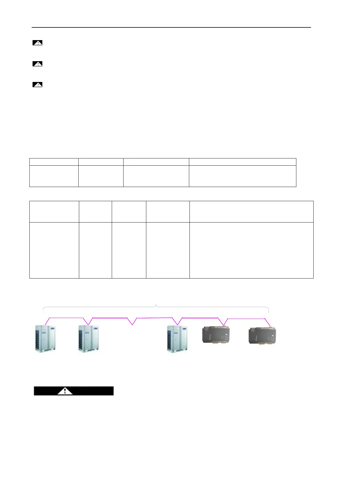
Note: The length of the CAN2 bus connecting the Modbus gateway with master ODUs should not
exceed 500 m, as shown in the following figure:
ODU system 2
Master ODU
ODU system n
Master ODU
ODU system 1
Master ODU
……
Modbus gateway
Max.: 500 m
CAN2 bus
―n‖ (n≤16) represents the quantity of the air conditioning systems.
2. Connection of Communication Lines
Only serial connection is allowed for all communication lines of the Modbus gateway. The star
connection is prohibited.
(1) Communication lines between the Modbus gateway and the Gree Web-based remote monitoring and
control system/BMS
 Loading...


