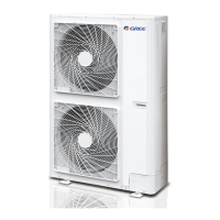
Do you have a question about the Gree GMV-80WL/A-T and is the answer not in the manual?
Details the available outdoor unit models, their codes, capacities, power supply, and refrigerant type.
Explains the coding system used to identify outdoor unit models and their specifications.
Overview of the DC Inverter Multi VRF System II, highlighting its advanced capabilities.
Highlights benefits such as high energy efficiency, CAN bus communication, long connection pipes, and wide operation range.
Provides detailed technical data for various outdoor unit models, including capacity, noise, and dimensions.
Specifies the cooling and heating operational temperature limits for the VRF system.
Guidance on adjusting unit capacity based on indoor and outdoor temperature conditions.
Instructions for correcting unit capacity based on refrigerant pipe length and height differences.
Details the schematic and interpretation of the unit's control logic and components.
Overview of the automatic central management system for air conditioning units.
Introduction to commissioning tool kits for monitoring, control, and maintenance of VRF systems.
Key preparation steps and safety notices for proper VRF system installation.
Guidelines for selecting appropriate materials like refrigerant piping, insulation, and cables.
Procedures for checking, selecting the site, and physically installing the outdoor unit.
Important considerations for proper placement, ventilation, and fixing of the outdoor unit.
Defines the necessary clearance and space requirements around the outdoor unit for proper operation.
Detailed steps and indicators for the unit's test run and debugging process.
A comprehensive list of display codes and their corresponding malfunctions for the wired controller.
Table explaining the meaning of status codes displayed by LEDs on the outdoor unit's main board.
Flowchart to diagnose and resolve communication issues between indoor and outdoor units.
Diagnostic steps for addressing high-pressure protection errors in the VRF system.
Guide to resolving low-pressure protection faults in the air conditioning unit.
Steps to identify and fix issues related to compressor discharge temperature protection.
Diagnosing problems with temperature sensors, general sensors, and unit power supply.
Procedure for diagnosing and resolving issues that prevent the unit from starting correctly.
Diagram illustrating the control logic and interconnections of major electrical parts within the unit.
Explanation of the function of key electrical components such as the filter plate and IPM module.
Reference electrical schematics for the outdoor unit for diagnostic purposes.
Illustrations and descriptions of essential components like the compressor, expansion valve, and 4-way valve.
Step-by-step instructions for safely removing major components from the outdoor unit.
| Brand | Gree |
|---|---|
| Model | GMV-80WL/A-T |
| Category | Air Conditioner |
| Language | English |


