Gree GMV6 DC Inverter VRF Units Service Manual
225
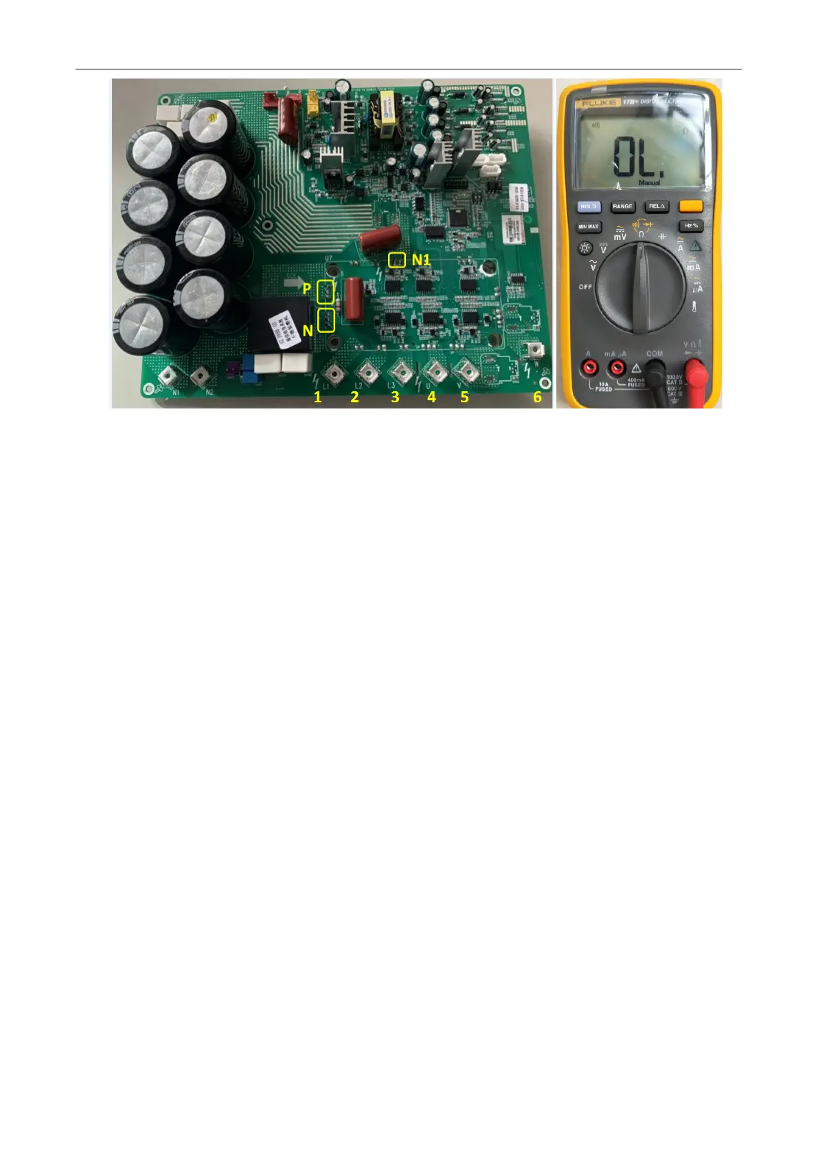
3:
Point the black probe to the P bonding pad and the red probe to the L2 wiring terminal. In the
normal condition, the multimeter will not beep. If it does, the drive board is damaged and needs to be
replaced.
4:
Point the black probe to the P bonding pad and the red probe to the L3 wiring terminal. In the
normal condition, the multimeter will not beep. If it does, the drive board is damaged and needs to be
replaced.
5:
Point the black probe to the P bonding pad and the red probe to the L1 wiring terminal. In the
normal condition, the multimeter will not beep. If it does, the drive board is damaged and needs to be
replaced.
6:
Point the black probe to the P bonding pad and the red probe to V wiring terminal. In the normal
condition, the multimeter will not beep. If it does, the drive board is damaged and needs to be replaced.
7:
Point the black probe to the P bonding pad and the red probe to the W wiring terminal. In the
normal condition, the multimeter will not beep. If it does, the drive board is damaged and needs to be
replaced.
8:
Point the black probe to the N bonding pad and the red probe to the L1 wiring terminal. In the
normal condition, the multimeter will not beep. If it does, the drive board is damaged and needs to be
replaced.
9:
Point the black probe to the N bonding pad and the red probe to the L2 wiring terminal. In the
normal condition, the multimeter will not beep. If it does, the drive board is damaged and needs to be
replaced.
10:
Point the black probe to the N bonding pad and the red probe to the L3 wiring terminal. In the
normal condition, the multimeter will not beep. If it does, the drive board is damaged and needs to be
replaced.
11:
Point the black probe to the N1 bonding pad and the red probe to U wiring terminal. In the normal
condition, the multimeter will not beep. If it does, the drive board is damaged and needs to be replaced.
12:
Point the black probe to the N1 bonding pad and the red probe to V wiring terminal. In the normal
 Loading...

