Do you have a question about the Gree GMV-S280W/A-X and is the answer not in the manual?
Details the technical specifications and performance parameters of outdoor units, hot water generators, and water tanks.
Guides on selecting appropriate models and collocations for various system configurations and operation modes.
Provides step-by-step guidance and examples for selecting system models based on user demand and conditions.
Explains the general control methods and provides a schematic diagram of the unit control system.
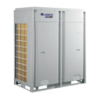
Provides detailed instructions for installing the Outdoor Unit (ODU), including dimensions, placement, and space requirements.
Covers the installation procedures, position, and space requirements for the Hydro Box.
Details the dimensions, installation position, and notices for installing the water tank.
Guidelines for designing, installing, and insulating refrigerant pipelines, including pipe sizes and connection methods.
Details the connection requirements and insulation for the hot water system pipeline.
Covers precautions and procedures for the electrical installation of the unit.
Explains the connection, way, and selection of communication cables for the system.
Provides procedures for installing power cables and selecting circuit breakers based on unit capacity.
Details precautions for refrigerant leakage and methods for calculating additional refrigerant charge.
Outlines the necessary tools and documents required before starting the commissioning process.
Details the steps for commissioning the hydro box and the entire unit.
Explains the function and settings of DIP switches for the GMV5 Unic outdoor unit.
Details the function DIP switch settings for GMV5 Unic outdoor units.
Covers functional dial switch settings and applications for the Hydro Box.
Lists and explains various error codes for outdoor units, indoor units, and hydro boxes.
Provides analysis and solutions for common system faults and errors.
Outlines routine checks and maintenance procedures for the outdoor unit, drain pipe, and system.
Details the procedure and precautions for vacuumizing the refrigerant system using a vacuum pump.
| Category | Inverter |
|---|---|
| Model | GMV-S280W/A-X |
| Cooling Capacity | 28.0 kW |
| Heating Capacity | 31.5 kW |
| Power Supply | 380-415V/3Ph/50Hz |
| Refrigerant | R410A |
| Operating Temperature Range (Cooling) | -5 to 48 °C |
| Outdoor Unit Dimensions (WxHxD) | 950 x 370 x 1380 mm |