GMV5 Home DC Inverter Multi VRF Units
219
standby status with display as below:
17_Commissioning
completed
The unit has completed
commissioning and in
standby status. LED1
displays module address.
LED2 and LED3 display OF.
Step 19: After commissioning is completed, set functions according to the actual engineering
requirements on functions. For specifc details, please refer to System Function Setting Method.
Skip this step if there is no special requirement.
Step 20: Deliver the product to user for use and inform users about usage precautions.
5. DIP Swith Instructions of GMV5 Unic
5.1 GMV5 Unic Outdoor Unit (GMV-S224W/A-X,GMV-S280W/A-X)
Application of outdoor unit functions includes function DIP switch setting and function button
setting, as well as special requirements used for the engineering.
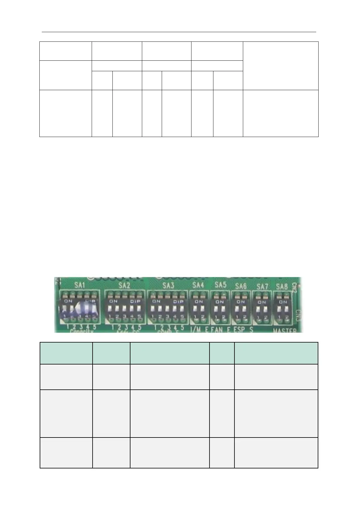
5.1.1 Function DIP Switch Settings
The function DIP switch settings are located at SA1~SA8 from AP1 of outdoor unit main board.
Below is the factory settings:
Defines the rated capacity of
the unit
The factory setting cannot be
changed.
Centralized
control
address DIP
switch
Defines and differentiates
addresses of different systems
in the case of centralized
control by multiple systems.
The address DIP switch is used
only when centralized control is
required. Otherwise, the factory
settings are used without being
changed.
Compressor
emergency
operation
Provides aftersales
emergency settings for 2#-6#
compressors.
It is better not to use the
emergency function. Replace
the compressor at the first time
 Loading...