Gree GMV6 DC Inverter VRF Units Service Manual
230
(1) Before the inspection: Find a correct digital multimeter and switch it to the diode gear. Power off
the unit and wait two minutes. Disconnect the U, V and W cables of the compressor and L1, L2
and L3 power cables from the drive board. Do not operate without waiting two minutes after the
unit is powered off.
(2) Testing method:
①
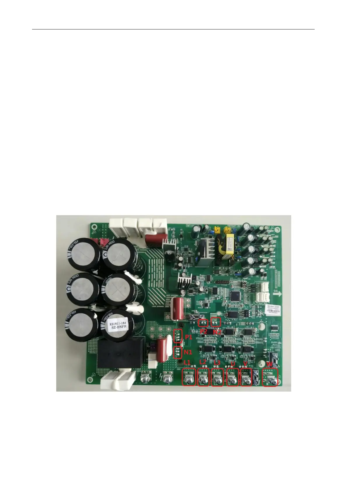
Point the black probe of the multimeter to the P1 bonding pad shown in the following figure
and the red probe to L1, L2 and L3 wiring terminals respectively and check the readings of the
multimeter; point the red probe of the multimeter to the N1 bonding pad shown in the following
figure and the black probe to L1, L2 and L3 wiring terminals respectively and check the readings
of the multimeter.
②
Point the black probe of the multimeter to the P2 bonding pad shown in the following figure
and the red probe to U, V and W wiring terminals respectively and check the readings of the
multimeter; point the red probe of the multimeter to the N2 bonding pad shown in the following
figure and the black probe to U, V and W wiring terminal respectively and check the readings of
the multimeter.
(3) Result analysis: If all the readings of the multimeter are between 0.3 V and 0.7 V in the above
12 conditions, the module is normal; if any of the readings is 0, the module is damaged.
 Loading...

