Gree GMV6 DC Inverter VRF Units Service Manual
271
(7) Install the unit panel.
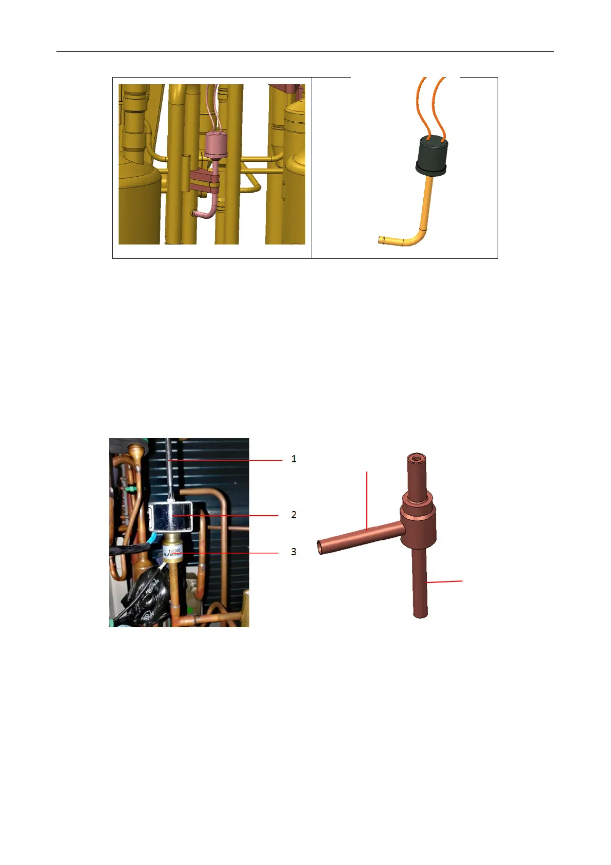
5.13 Preparation for Removing and Installing Solenoid Valve
Steps:
(1) Use the power circuit breaker to switch off the power of the GMV6 VRF system.
(2) Make sure that the unit pipeline system is free of refrigerant.
(3) Remove the unit’s upper and bottom panels by referring to 5.1.1 Removing the Unit Panel.
Removing procedure
(1) Use a tool to remove the solenoid valve coil.
(2) Use a pipe cutter to cut off the solenoid valve inlet and outlet pipes and remove the valve body.
Cut-off point
Cut-off point
(3) Use gas welding to heat the pressure switch connection port and pull out the solenoid valve inlet
and outlet pipes. Nitrogen protection should be applied during welding; the nitrogen pressure is
0.5±0.1kgf/cm2 (relative pressure).
(4) Weld and take off the old solenoid valve inlet and outlet pipes from the pipeline.
Installation procedure
(1) Install the new solenoid valve to the exact position.
(2) Wrap the solenoid valve with a damp cloth.
(3) Adopt nitrogen protection during welding. The nitrogen pressure is 0.5±0.1kgf/cm2 (relative
 Loading...

