Gree GMV6 DC Inverter VRF Units Service Manual
4.1.4 DIP Switch Examples
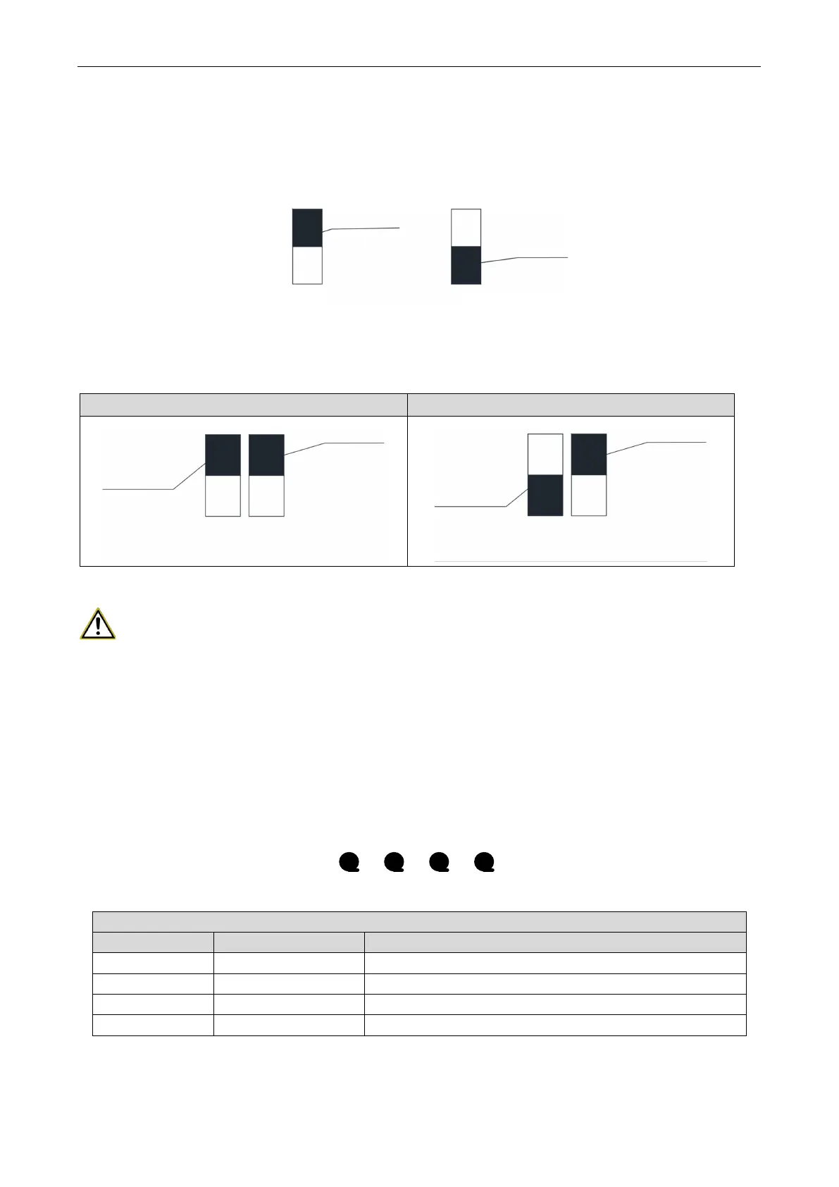
(1) DIP switch position description
DIP switch at the ON end indicates 0; DIP switch at the other end indicates 1.
The white lever is DIP switch position.
White lever
position
"0" status "1" status
White lever
position
ON ON
(2) Example
This example describes master module settings. If a system has three modules, namely modules a,
b and c, to set module c to the master module and the other two modules to submodules, do as follows:
Module c (master module) Modules a and b (submodules)
White lever
position
White lever
position
ON
0 0
SA8_MASTER-S
White lever
position
White lever
position
ON
1 0
SA8_MASTER-S
4.2 System Function Operations
CAUTIONS!
①
System function settings and queries must be performed after the entire system is
commissioned.
②
System function settings and queries can be performed regardless of whether the entire
system is running or not.
4.2.1 Function Buttons
There are four function buttons on the main board of the outdoor unit, as shown below:
SW1 SW2 SW3 SW4
Up
▲
Down
▼
BackConfirm
Names and Functions of the Buttons
Button No. Code Function
SW1 Up Selects the upper item.
SW2 Down Selects the lower item.
SW3 Confirm Confirms the selection.
SW4 Back Returns to the previous operation.
 Loading...
