GMV5 DC INVERTER VRF UNITS SERVICE MANUAL
182
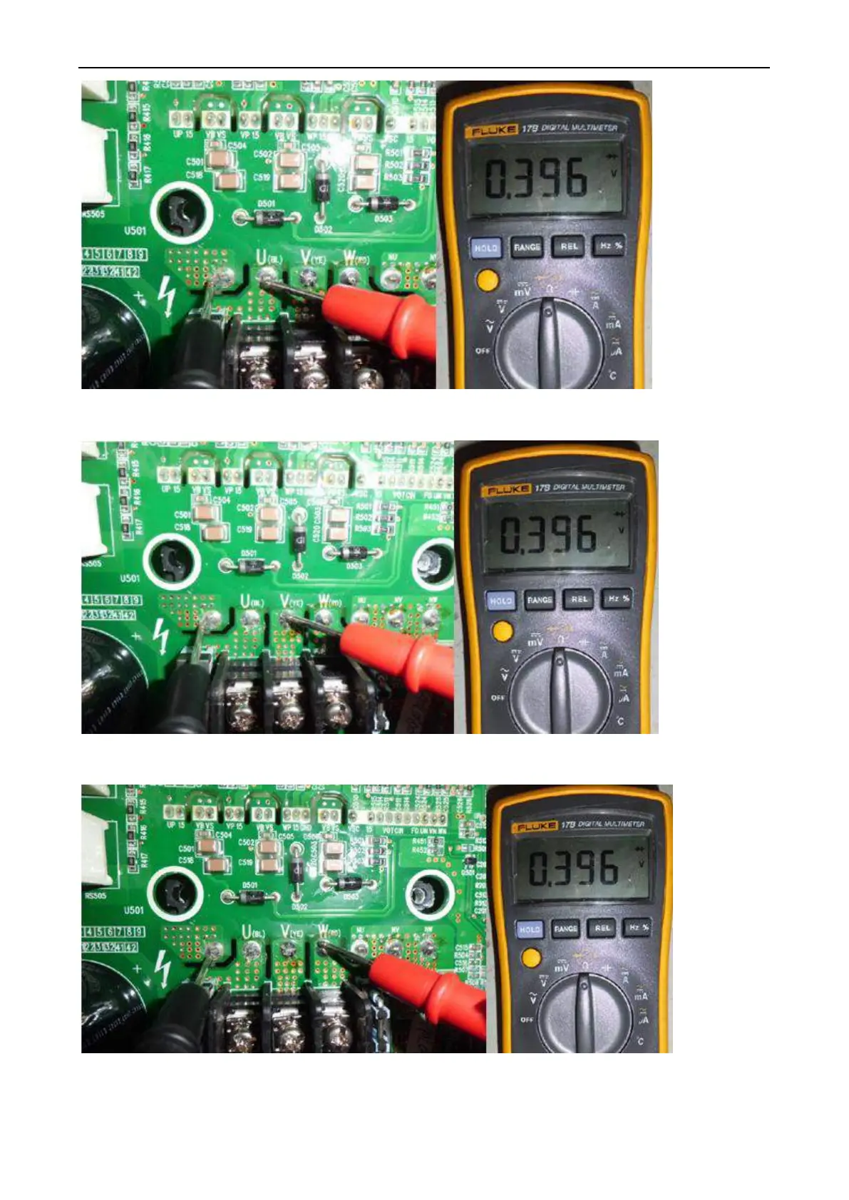
3. As shown in the figure below, put the black test probe to pad P and the red test probe to pad V (YE)
(make sure the moisture proof tape is removed). In normal cases, the multimeter should read 0.39±0.3 V.
If it is ―0‖ or infinitely great, the IPM module is faulty.
4. As shown in the figure below, put the black test probe to pad P and the red test probe to pad W (RD)
(make sure the moisture proof tape is removed). In normal cases, the multimeter should read 0.39±0.3 V.
If it is ―0‖ or infinitely great, the IPM module is faulty.
5. As shown in the figure below, put the black test probe to pad U (BL) and the red test probe to pad NU
(make sure the moisture proof tape is removed). In normal cases, the multimeter should read 0.39±0.3 V.
If it is ―0‖ or infinitely great, the IPM module is faulty.
 Loading...


