GMV5 DC INVERTER VRF UNITS SERVICE MANUAL
58
The minimum distance between supports, hangers, and brackets is listed in the table below:
External Diameter of the
Pipe (mm)
Distance between
Horizontal Pipes (mm)
Distance between Vertical
Pipes (mm)
The pipe led through a wall or beam must be fixed by a support, hanger, or bracket on both ends at
the position 300 mm away from the hole.
3.4 Pipe Connection
3.4.1 Flaring Connection
The refrigerant pipes and IDUs are connected by using the flare opening. Therefore, the quality of
flaring connection must be ensured. The flaring depth of the bell mouth cannot be smaller than the
caliber. The flaring direction must face towards the direction of medium flow. Use two torque wrenches to
fasten the connection.
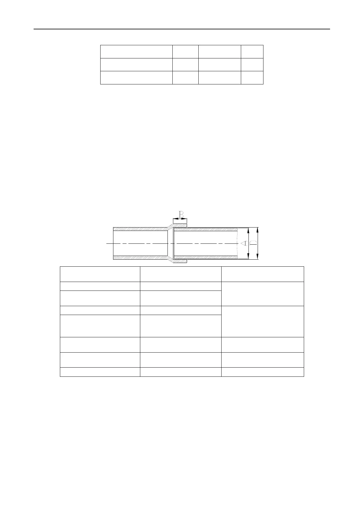
3.4.2 Socket Welding
The gap between socket components should be proper to ensure that the connection will not loose
from the friction surface. The flaring direction of the socket component must face towards the direction of
medium flow .During pipe connect, protect the braze welding part according the length specified below:
A: External Diameter of
the Pipe (mm)
B: Minimum Insertion
Depth (mm)
D-A: Gap between Pipes
(mm)
3.4.2 Bell Socket Welding
The bell socket welding is another form of socket welding. It uses the sleeve or pipe in a larger size
for welding. The insertion depth cannot be smaller than that required by socket welding.
3.4.5 Flange Connection
The pipes with large caliber and the devices are always connected by using a flange, which must be
clean and intact. Before installation, apply lubricant on the surface of the flange. Two flanges must be
symmetrical. Fasten with screws at the diagonal direction to avoid inclination.
3.5 Welding Protection
Aerate with nitrogen before and during welding and keep aerating for 30 s after the welding is
finished.
 Loading...


