GMV5 DC INVERTER VRF UNITS SERVICE MANUAL
65
1.3 Procedure of Insulation
a. Select insulation materials based on design requirements.
b. Wear the insulation sleeve before connecting refrigerant pipes. Users cannot cut the insulation
material apart and then wrap up with ties after connecting the pipes by welding.
c. Specifications of the insulation sleeve must match with that of the refrigerant pipes.
d. Reserve a distance of about 200 mm near the welding point to protect the insulation sleeve during
welding. After performing the air-tightness test, perform insulation to the welding point separately to
ensure continuity of the insulation sleeve.
e. The insulation layer cannot crack during construction. Bond the insulation material joints with special
glue and then wrap them with electrical adhesive tape. The width of the adhesive tape must be 50 mm or
more to ensure secure connection.
f. Use glue to bond the insulation material at the water outlet to the unit to prevent dewing.
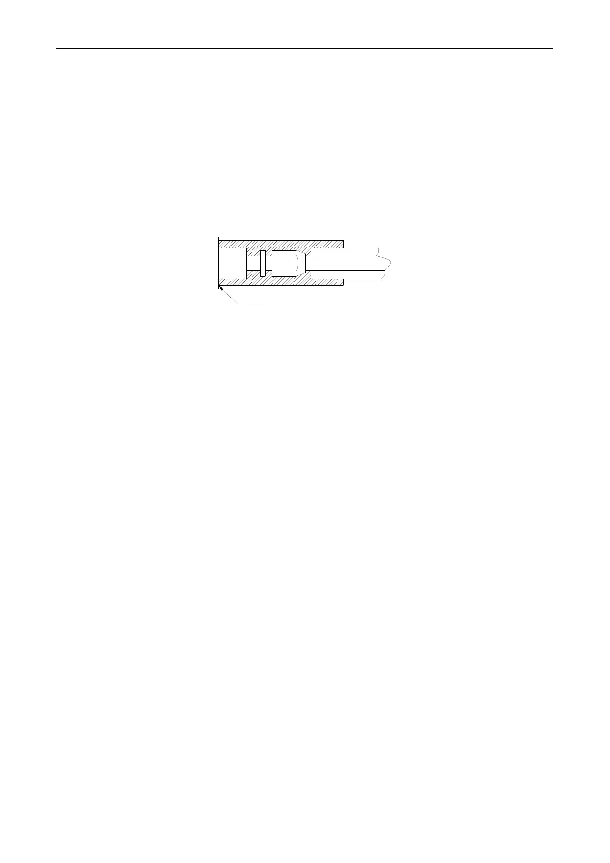
g. Wrap joints of indoor/outdoor units with insulation materials. There must be no gap between the joint
and the wall of the indoor/outdoor unit, as shown in the following figure.
2. Insulation for the Condensate Water Pipe System
2.1 Insulation Materials
Use closed-cell foam insulation materials with retardant grade of B1.
The heat conductivity is not greater than 0.035 w/(m·k) when the average temperature is 0 °C .
2.2 Thickness of the Insulation Layer
Thickness of the insulation layer for the condensate water pipe must be greater than 10 mm.
2.3 Bond the insulation material joints with special glue and then wrap them with plastic adhesive. The
width of the adhesive must be greater than 5 cm to prevent dewing.
2.4 Insulation is not required for the outdoor part of condensate water pipes.
3. Insulation for Air Ducts
3.1 Insulation for air duct components and devices must be performed after the air leakage test is
performed or after quality check.
3.2 Use centrifugal glass wool or rubber and plastic materials for insulation or use novel insulation air
ducts.
3.4 The insulation layer should be flat and tight without any crack or gap.
3.5 Thickness of the Insulation Layer
For the air supply and return air pipe laid in a room without an air conditioner, thickness of the rubber and
plastic insulation layer is 35 mm.
For the air supply and return air pipe laid in an air conditioning room, thickness of the rubber and plastic
insulation layer is 20 mm.
3.6 Supports, hangers, and brackets of the air duct must be installed outside the insulation layer. A chock
must be provided between the support, hanger, or brackets and the air duct.
 Loading...


