GMV5 DC INVERTER VRF UNITS SERVICE MANUAL
67
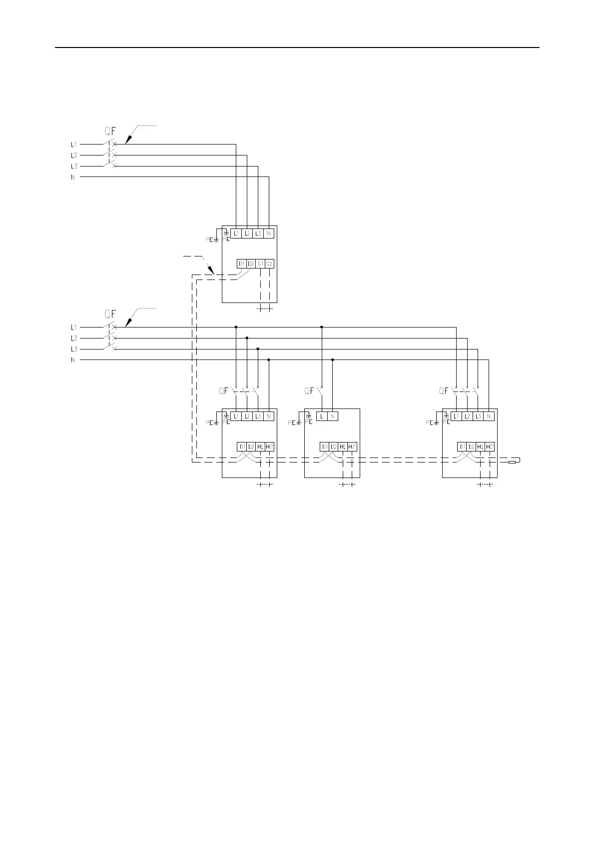
2. Requirements on Power Cable Configuration
Configure a circuit breaker to each unit for short circuit and overload protection. In addition, configure a
general circuit breaker to both the indoor and ODUs to switch on or switch off the general power of the
IDU or ODU.
1) External Connection for Individual Units
Power
Power
Power cable
Power
cable
Communication cable
Outdoor unit 1
(master module)
Remote monitoring
Indoor unit 1
Wired controller
Indoor unit 2
The last
indoor unit
Indoor unit n
Wiring (with
matching resistor)
Wired controller
Wire controller
Power terminal block XT1
Communication
terminal block XT2
Power terminal block XT1
Communication
terminal block XT2
Power terminal
block XT1
Communication
terminal block XT2
Power terminal block XT1
Communication
terminal block XT2
Note:
The maximum number of connected IDUs (n) is determined based on the capacity of the ODU. For
details, see the description on unit capacity configuration.
2) External Connection for Modularly Connected Units
 Loading...


