GMV5 DC INVERTER VRF UNITS SERVICE MANUAL
87
Note: The highest daytime temperature is generally in 13:00-15:00.
For the forcible silent mode, the system runs in low-noise mode no matter in the daytime or nighttime.
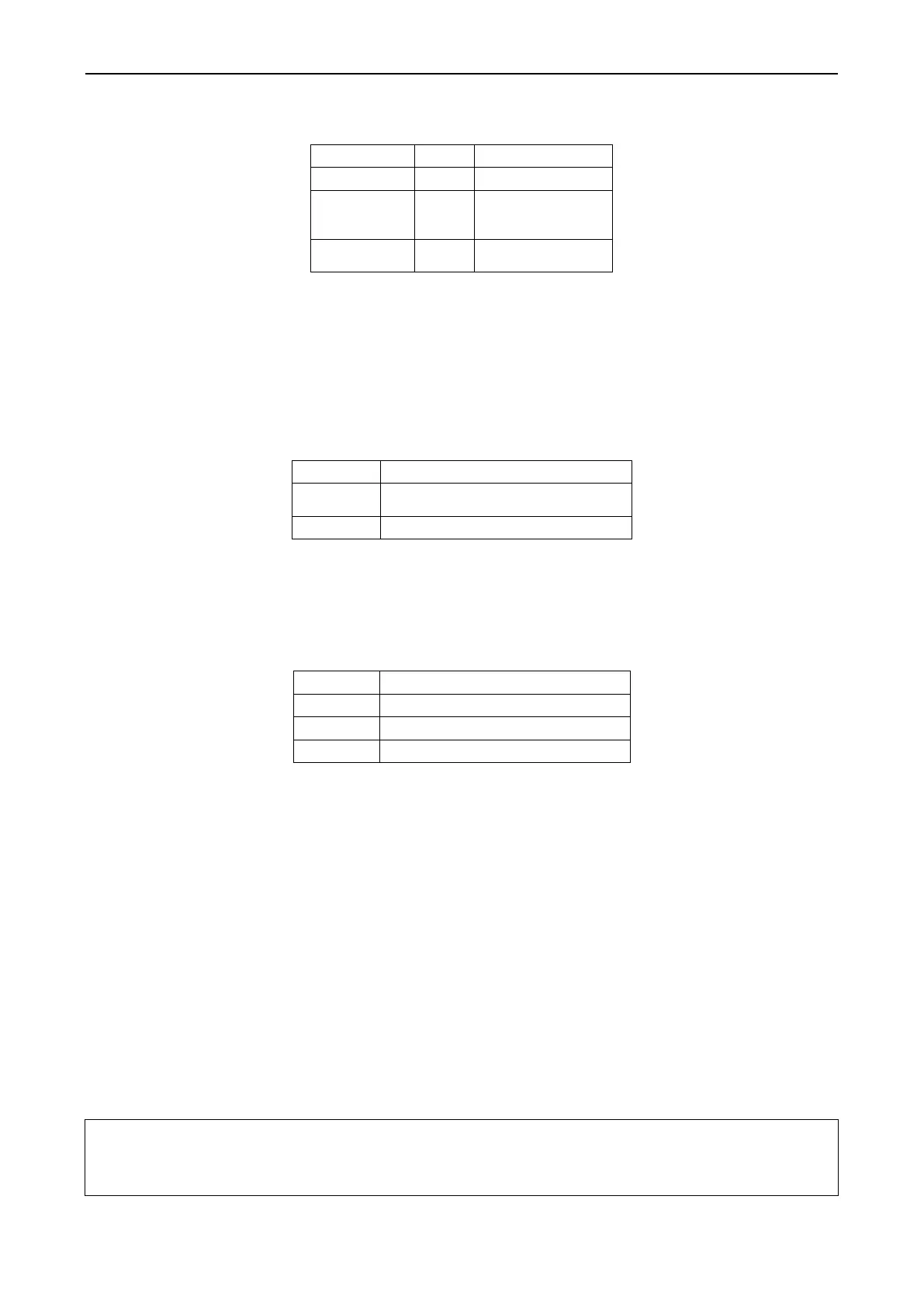
The forcible silent mode falls in three categories:
Low- and
medium-noise
mode
Note: The system capacity may fall off after the silent mode is set. Therefore, try to balance the noise
with the capacity in selecting a silent mode category.
The factory setting is ―00‖.
(4) A8 Aftersales vacuuming mode
This function ensures the vacuum degree of the entire system during maintenance to prevent operation
functions of dead zones. Expansion valves and electromagnetic valves of the unit will be enabled after
this function is set.
(5) n0 Conservation control 1
System conservation is set when conservation operations are required. The default factory setting is
capacity priority control mode. The system capacity may fall off after the conservation mode is set.
Conservation control – invalid (factory
settings)
Conservation control - valid
(6) n3 Forcible defrosting operation
This function is set when forcible defrosting is required for the unit during maintenance. After this
function is enabled, the system automatically quits based on quitting conditions and then automatically
runs based on system conditions.
(7) n4 Conservation control 2
The highest capacity output limitation is set when users require forcibly limiting the system power
consumption. The setting scope is as follows:
Note: The cooling or heating effect may fall off after the capacity limitation is set.
(8) n5 Indoor unit project number offset
This function sets the IDU project number when multiple refrigerating systems are controlled in a
centralized manner (by using a remote monitor or centralized controller), avoiding the same project
number between different systems. If the project number is not set, project number conflicts may occur
between systems.
This function only needs to be set on the master system, which is the system with the centralized control
address SA2 DIP switch being ―00000‖. For details, see the "Centralized Control Address DIP Switch
(SA2_Addr-CC)" section.
(9) n6 Fault query
This function queries historical faults of the system. Up to five historical faults can be memorized in time
order.
(10) n7 Parameter query
This function queries operation parameters of each module of the ODU in real time.
(11) n8 Indoor unit address query
This function queries addresses of all IDUs through one operation of the ODU.
(12) n9 Online IDU quantity query
This function queries the number of online IDUs through the ODU.
3. Function Setting Operations
Step 1: Open the commissioning window of the master unit panel.
Step 2: Power on the entire unit.
Step 3: Press "SW3" on the master unit to enter the to-be-selected status of function settings. By default,
the master unit is displayed as follows:
 Loading...


