GREE DC Inverter Multi VRF System II Service Manual
74
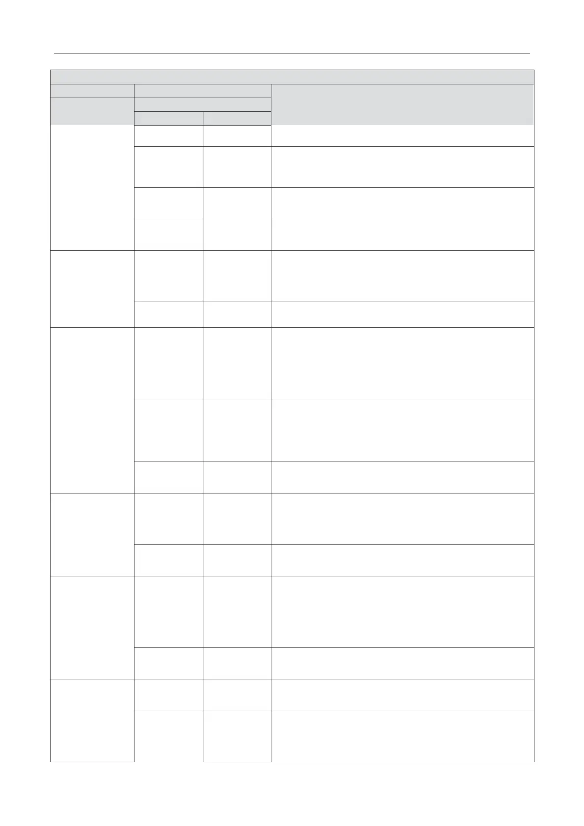
Description of each stage of debugging progress
Code meaning and operation method
Progress
power is off during troubleshooting, then restart debugging from
progress 01 after power is on.
05/oC
Communication of master ODU and driver is normal. Unit will
display as in the left for 2s and detect the capacity ratio of IDU
and ODU. If the ratio is within range, than next step will start 2s
later. If the ratio is out of range, unit will display as below:
05/CH
Rated capacity ratio of IDU is too high. Change the combination
way of
IDU and ODU to make the ratio within range. And restart
debugging from progress 01.
05/CL
Rated capacity ratio of IDU is too low. Change the combination
way of IDU and ODU to make the ratio within range. And restart
debugging from progress 01.
outdoor
components
Outdoor component’s error. Besides “06”, the other blinking will
display the related error code. After errors are eliminated,
system will start next step automatically. If power is off during
troubleshooting, then restart debugging from progress 01 after
power is on.
06/oC
System detects no error on outdoor component. 10s later, next
step starts.
components
code
Displa
System detects error on indoor components. XX means the
project code of IDU with error, e.g. no.1 IDU has d5 and d6
errors, meanwhile no.3 IDU displays error d6 and d7, then the
nixie tube will display “07”, “01”, “d5”, “d6”and “03” circularly
.
After errors are eliminated, system will start next step
automatically. If power is off during troubleshooting, then restart
debugging from progress 01 after power is on.
code
If errors occur in IDU which the project code is ı 3-digit
number, then it will display the 2 big digits of project code first,
then the 2 small digits, finally the error code, e.g: L1 error occurs
in no.101 IDU, then the nixie tube will display “01”,“01” and “L1”
circularly. Display
method is the same for several IDUs with
07/oC
No error on components of IDU. 5s later, next step starts.
preheated
compressor
08/U0
Preheat time for compressor is less than 8 hours. Display will be
as in the left until the preheat time reaches 8 hours. Press main
board’s SW3 button to confirm manually that the preheat time
has reached 8 hours. Then start next step. (Note: Compressor
may get damaged if it is started without 8 hours of preheat time)
08/oC
Compressor has been preheated for 8 hours. 2s later, next step
starts.
09_ Refrigerant
judgments before
startup
09/U4
System is lack of refrigerant and display will be as in the left.
Please cut off power of IDU and ODU and check if there is
leakage on pipeline. Solve the leakage problem and complement
refrigerant into the unit. Then connect power and restart
debugging from progress 01. (Note: Before re
-charging
must be power off in case system starts progress
10 automatically.)
09/oC
Refrigerant is normal and unit will display as in the left for
2s.Then next step starts.
10_ Status
judgments of
outdoor valves
before startup
10/on
Valves of ODU are being inspected. Compressor will start
operation for 2min or so and then stop. The opening and closing
status of outdoor valves are as below:
10/U6
Outdoor valves are not fully turned on. Press main board’s SW4
button and display shows “09/OC”. Then check if the gas and
liquid valves of ODU are completely open. After confirmation,
press the SW4 button again. Then compressor will start running
for about 2min to inspect the status of valves.
 Loading...

