Gree GMV6 DC Inverter VRF Units Service Manual
204
4.3.1 Mechanical Inspection
(1) Confirm that the unit Power is disconnected.
(2) Find the 4-way valve or solenoid valve, check whether the fixing screw is loose and whether the
valve and coil have any apparent exceptions.
4.3.2 Electrical Inspection
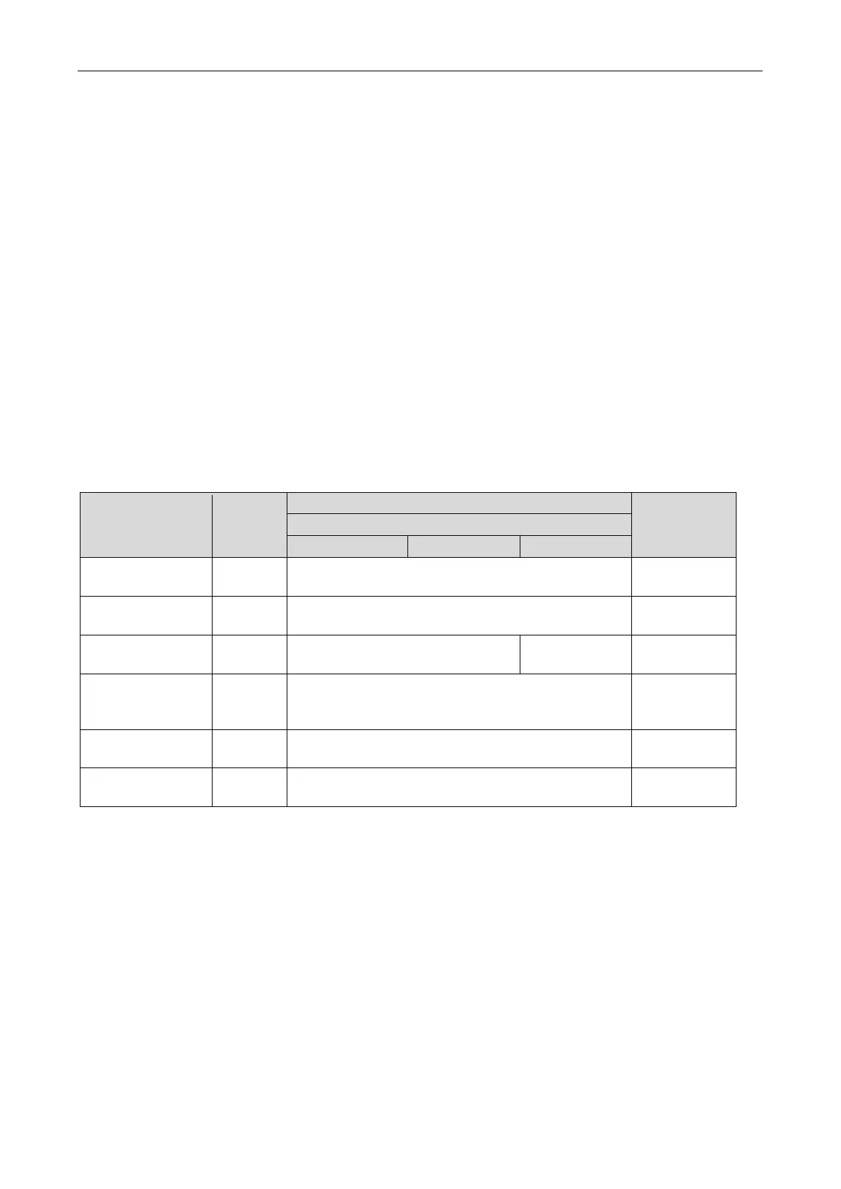
Compare the measured coil resistance with the normal coil resistance to check whether the coil is
damaged.
(1) Power off the unit. Remove the electrical appliance cover after the ODU stops.
Warning: Electric shock
(2) Remove the electrical appliance cover and check whether the connecting terminal of the 4-way
valve or solenoid valve is firm.
(3) Disconnect the corresponding valve's coil terminal from the main board and use a multimeter to
measure the coil resistance.
(4) If the measured resistance does not match with that in the following table, the coil needs to be
replaced.
Coil
Bolt on
the main
board
Normal
range of
deviation
CN23 2085 ±10%
Oil-return
solenoid valve 1
CN24 2085 ±10%
Oil-return
solenoid valve 2
CN25 — 2085 ±10%
oil-return
CN26 2085 ±10%
CN27 1273 ±10%
CN30 2085 ±10%
 Loading...
