EasyManuals Logo

Gree GMV-950WM/G-X User Manual

Gree GMV-950WM/G-X
74 pages
To Next Page IconTo Next Page
To Previous Page IconTo Previous Page
Page #27 background imageLoading...
Page #27 background image
GMV DC Inverter VRF
23
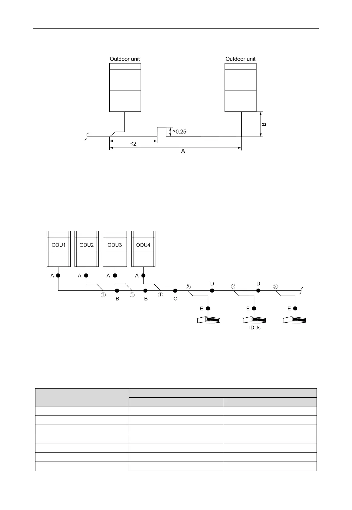
(2) The drop and the length of the pipe between the outdoor units are as follows.
Unit: m
Fig.3.3.7
Note
When the distance A+B between the outdoor modules exceeds 2m, U-type oil trap should be
added at low-pressure gas pipe and is no more than 2m away from the outdoor manifold, and
A+B≤10m. The height drop among the outdoor units is 0m.
3.3.5 Pipe Selection
Fig.3.3.8
(1) When its modular units connection, the ODU must be installed in capacity order: ODU 4ODU
3ODU 2ODU 1.
(2) Pipe "A" between the outdoor unit and the manifold of outdoor unit.
The pipe size is based on the capacity of upstream module.
Basic module
Pipe between ODU and the first branch of IDU
Gas pipe(mm)
Liquid pipe(mm)
GMV-224WM/G-X
Φ19.05
Φ9.52
GMV-280WM/G-X
Φ22.2
Φ9.52
GMV-335WM/G-X
Φ25.4
Φ12.7
GMV-400WM/G-X
Φ25.4
Φ12.7
GMV-450WM/G-X
Φ28.6
Φ12.7
GMV-504WM/G-X
Φ28.6
Φ15.9
GMV-560WM/G-X
Φ28.6
Φ15.9

Other manuals for Gree GMV-950WM/G-X

Questions and Answers:

Question and Answer IconNeed help?

Do you have a question about the Gree GMV-950WM/G-X and is the answer not in the manual?

Gree GMV-950WM/G-X Specifications

General IconGeneral
BrandGree
ModelGMV-950WM/G-X
CategoryInverter
LanguageEnglish

Related product manuals