GMV DC Inverter VRF
59
Meaning
Progress
Code
Display
Display
Cod
Display
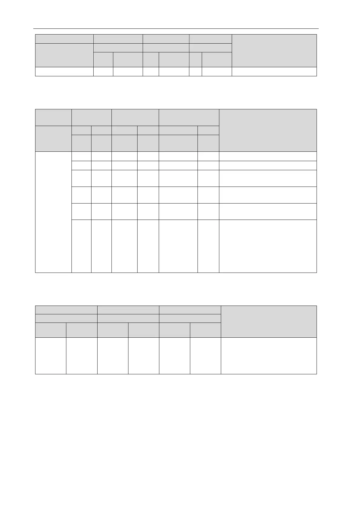
Step 16: After the unit debugging method is confirmed, the system automatically selects cooling
or heating mode according to the ambient temperature.
Once cooling/heating mode is selected, the relevant display is as below.
—
Debugging
Progress code Status code
Meaning
Progress
Code
Code
Display
Code
13~15_ pilot
run stage
Pilot run of cooling mode
Pilot run of heating mode
db ON
13/14/15
ON
ON
There’s fault on pilot run stage.
Note: fault module display
db ON
13/14/15
ON J0 ON
There’s fault on pilot run stage.
Note: non-fault module display
db ON
13/14/15
ON U9 ON
Outdoor unit’s pipeline or valve is
db ON 13/14/15 ON XXXX/U8 ON
The system detected the indoor unit’s
pipeline is abnormal. XXXX indicates
engineering number of fault indoor unit.
2s later, U8 fault occurred for No. 100
indoor unit. LED3 will display as below:
01 (2s later) 00 (2s later) U8, and it will
display like that circularly.
Note:
In the pilot run stage, the unit will display corresponding procedures according to actual
circumstances.
Once debugging is completed, resume the standby status and the display is as below:
Meaning
Code
Display
Code
Display
Code
Display
01~04 ON OF ON OF ON
The complete unit has finished the
debugging and it stays at standby
status. LED1 displays module
address; LED2 and LED3 displays
Once the debugging for the complete unit is finished, please set relevant functions for the unit
according to the actual functional requirements of the project. Refer to relative technical materials for
the detailed operation method. If there is no special requirement, skip this step directly.
When delivery it to the user for operation, explain the precautions to the user.
 Loading...
