OPERATING INSTALLATION MANUAL FOR AHU-KIT UNIT
20
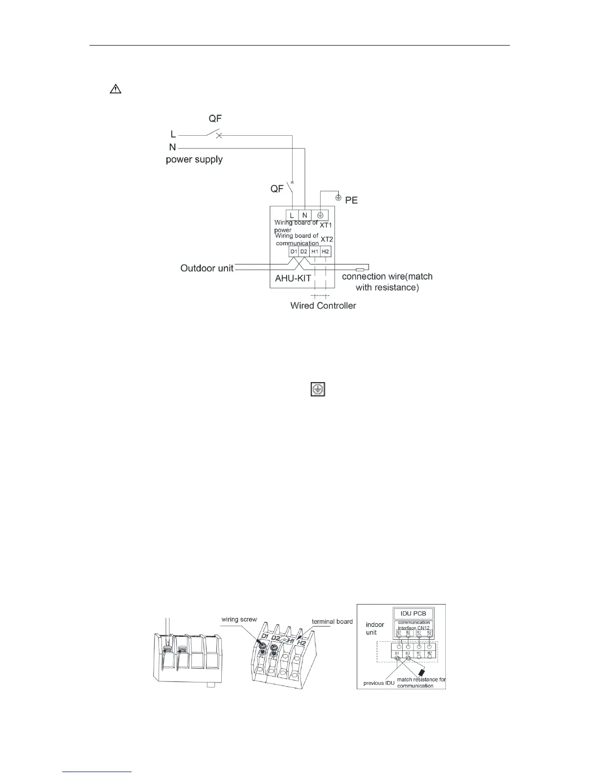
5.2 Power Cord Connection
Notes!
Power supply of each indoor unit must be from the same source.
Fig.5.2
For units with single-phase power supply:
1) Detach the electric box lid.
2) Let the power cord pass through the wiring through-holes.
3) Connect the power cord to terminal “L, N, ”.
4) Fix the power card with wiring clamp.
5.3 Connection of Communication Wire between Indoor Unit and
Outdoor Unit (or Indoor Unit)
1) Detach the control box lid.
2) Let the Communication cable pass through the wiring through-holes.
3) Connect the communication wire to terminal D1 and D2 of indoor 4-bit wiring board, as
shown in fig.5.3.1.
4) Fix the communication cable with clamp of electric box.
5) For more reliable communication, make sure connect the terminal resistor to the most
downstream IDU of the communication bus (terminal D1 and D2), as shown in fig 5.3.2,
terminal resistor is provided with each ODU.
Fig.5.3.1 Fig.5.3.2
 Loading...