OPERATING INSTALLATION MANUAL FOR AHU-KIT UNIT
8
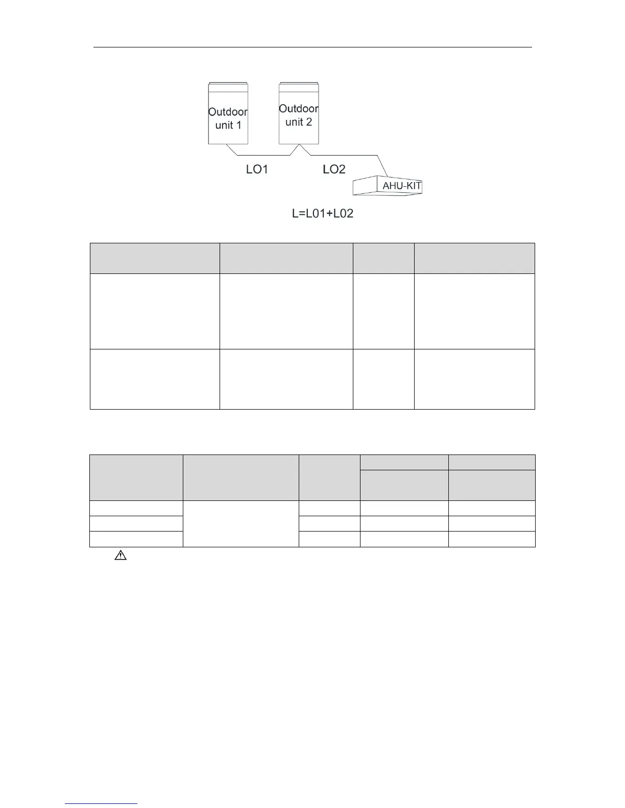
3.6.2 Select Communication wire for AHU-KIT and Outdoor Unit
Fig.3.6.2
Total Length of Communication
wire L(m)
Light/Common PVC Jacket
Soft Wire
If wire gauge is 2X1 mm
2
,
then it’s OK to increase the
length of communication
wire. But total length should
not exceed 1500m.
Light shield/Common PVC
Jacket Soft Wire
The shield cable is required
when the unit is installed in
the environment of strong
magnetic or interference.
3.7 Wiring Requirements
Power Cord Size and Air Switch Capacity:
Minimum Sectional
Area(mm
2
)
Minimum Sectional
Area(mm
2
)
220~240V/1ph/50Hz &
208~230V/1ph/60Hz
Notes:
① Use copper wire only as unit’s power cord. Operating temperature should be within its
rated value.
② Above selection requirements: Power cord size is based on BV single-core wire (2~4pc)
at 40°Cambient temperature when laying across plastic pipe. Air switch is D type and
used at 40°C. If actual installation condition varies, please lower the capacity
appropriately according to the specifications of power cord and air switch provided by
manufacturer.
③ Install cut-off device near the unit. The minimum distance between each stage of cut-off
device should be 3 mm (The same for both indoor unit and outdoor unit).
 Loading...