EasyManua.ls Logo

Gree GMV-ND45PHS/B-T - User Manual

Gree GMV-ND45PHS/B-T
28 pages
Print Icon
To Next Page IconTo Next Page
Loading...
Owner's Manual
Original Instructions
Commercial Air Conditioners
Multi Variable Air Conditioners
Ducted Type Indoor Unit
Models:
GMV-ND22PHS/B-T GMV-ND25PHS/B-T GMV-ND28PHS/B-T GMV-ND32PHS/B-T
GMV-ND36PHS/B-T GMV-ND40PHS/B-T GMV-ND45PHS/B-T GMV-ND50PHS/B-T
GMV-ND56PHS/B-T GMV-ND63PHS/B-T GMV-ND71PHS/B-T GMV-ND80PHS/B-T
GMV-ND90PHS/B-T GMV-ND100PHS/B-T GMV-ND112PHS/B-T GMV-ND125PHS/B-T
GMV-ND140PHS/B-T GMV-ND160PHS/B-T GMV-ND180PHS/B-T

Other manuals for Gree GMV-ND45PHS/B-T

Questions and Answers

Summary

Exception Clauses

Safety Notices

Understanding Safety Symbols and Warnings

Explains safety symbols and general warnings for unit and personal safety.

Installation & Operation Precautions

Guidelines for proper installation, grounding, and operational safety.

Product Introduction

Names of Key Components

Identifies and labels the main parts of the indoor unit.

Rated Working Condition

Specifies the operational temperature and humidity ranges for cooling and heating.

Preparations for Installation

Standard Fittings

Lists and describes the standard fittings provided for installation.

Location for Installation

Recommendations for choosing an appropriate and safe installation site for the unit.

Requirements for Communication Line

Select Communication Line for Indoor Unit and Wired Controller

Specifies cable types and connection methods for indoor units and wired controllers.

Wiring Requirements

Power Cord Size and Air Switch Capacity

Details on selecting appropriate power cords and air switch capacities for safe operation.

Installation Instructions

Outline Dimension and Installation Spots

Provides dimensions and recommended locations for indoor unit installation.

Suspend the indoor unit

Instructions on how to properly hang and secure the indoor unit using bolts and brackets.

Refrigerant Pipe Connection

Procedures for connecting refrigerant pipes, including torque specifications.

Drainage Pipe Installation and Drainage System Testing

Notice for Installation of Drain Pipe

Important considerations and prohibitions for drain pipe installation to prevent issues.

Drainage Pipe Installation

Step-by-step instructions for physically installing the drain hose and related components.

Test of Drainage System

Procedures for testing the drainage system to ensure proper water flow and leak prevention.

Installation of Air Duct

Installation of Air-out Duct

Details on the shape, size, and installation of the air outlet duct.

Installation of the Return Air Duct

Instructions for connecting and installing the return air duct to the unit.

Installation of the Fresh Air Pipe

Steps for connecting and installing the fresh air duct, including baffle modifications.

Installation of Wired Controller

Wiring Work

Connection of Wire and Patch Board Terminal

Procedures for connecting wires to terminals and patch boards.

Power Cord Connection

Instructions for connecting the main power cord to the unit.

Connection of Communication Wire between Indoor Unit and Outdoor Unit (or indoor unit)

How to connect communication wiring between indoor and outdoor units.

Connect Communication Wire of Wired Controller

Steps for connecting communication wires for the wired controller.

Illuminate for Connection of Wired Controller and Indoor Units Network

Explains how to connect wired controllers and indoor units in a network.

Setting of External Static Pressure

Routine Maintenance

Cleaning of Filter

Instructions for cleaning the air filters of the indoor unit.

Maintenance before the Seasonal Use

Checks to perform on the unit before the start of the cooling or heating season.

Maintenance after the Seasonal Use

Procedures for preparing the unit for storage after the season ends.

Table of Error Codes for Indoor Unit

Troubleshooting

Overview

This document serves as the Owner's Manual for Gree Commercial Air Conditioners, specifically focusing on Multi Variable Air Conditioners with Ducted Type Indoor Units. It provides essential information for installation, operation, and maintenance to ensure safe and correct usage of the product.

Function Description:

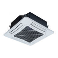
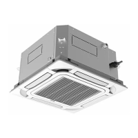
The device is a commercial air conditioner, part of Gree's Multi Variable Refrigerant Flow (VRF) system, designed for ducted indoor unit applications. Its primary function is to provide heating and cooling for commercial spaces, ensuring a comfortable indoor environment. The system allows for multiple indoor units to be connected to a single outdoor unit, offering flexibility and energy efficiency for various building layouts and demands. The ducted type indoor unit is designed for concealed ceiling installation, allowing for discreet integration into the building's aesthetics while delivering conditioned air through a ductwork system.

Important Technical Specifications:

The manual lists several models of ducted type indoor units, including:

  • GMV-ND22PHS/B-T
  • GMV-ND25PHS/B-T
  • GMV-ND28PHS/B-T
  • GMV-ND32PHS/B-T
  • GMV-ND36PHS/B-T
  • GMV-ND40PHS/B-T
  • GMV-ND45PHS/B-T
  • GMV-ND50PHS/B-T
  • GMV-ND56PHS/B-T
  • GMV-ND63PHS/B-T
  • GMV-ND71PHS/B-T
  • GMV-ND80PHS/B-T
  • GMV-ND90PHS/B-T
  • GMV-ND100PHS/B-T
  • GMV-ND112PHS/B-T
  • GMV-ND125PHS/B-T
  • GMV-ND140PHS/B-T
  • GMV-ND160PHS/B-T
  • GMV-ND180PHS/B-T

Rated Working Conditions:

  • Rated Cooling: Indoor Dry Bulb Temp 27°C, Wet Bulb Temp 19°C; Outdoor Dry Bulb Temp 35°C, Wet Bulb Temp 24°C.
  • Rated Heating: Indoor Dry Bulb Temp 20°C, Wet Bulb Temp 15°C; Outdoor Dry Bulb Temp 7°C, Wet Bulb Temp 6°C.

Communication Line Requirements:

  • For indoor unit and wired controller: Total length L (m) ≤ 250m, Wire size 2×0.75~2×1.25 mm², Material Standard IEC 60227-5. The cord should be circular with twisted cores. Shielded wire is recommended in environments with intense magnetic fields or strong interference.
  • For indoor unit and indoor (outdoor) unit: Total length L (m) ≤ 1000m, Wire size ≥ 2×0.75 mm², Material Standard IEC 60227-5. If wire diameter is enlarged to 2×1 mm², total communication line length can reach 1500m. Shielded wire is recommended in environments with intense magnetic fields or strong interference.

Power Cord Size and Air Switch Capacity:

For GMV-ND22~180PHS/B-T models:

  • Power Cord Size: 220~240V-1ph-50Hz or 208~230V-1ph-60Hz
  • Air Switch Capacity: 6A
  • Minimum Sectional Area of Ground Wire: 1.0 mm²
  • Minimum Sectional Area of Power Cord: 1.0 mm² Copper wire only should be used for power cords, with operating temperature within rated value. For power cords longer than 15m, the sectional area should be increased.

Installation Dimensions (Unit: mm):

Model A B C D E F G
GMV-ND22~50PHS/B-T 740 500 830 300 754 700 700
GMV-ND56~80PHS/B-T 1040 500 1130 300 754 1000 700
GMV-ND90~125PHS/B-T 1440 500 1530 300 754 1400 700
GMV-ND140~180PHS/B-T 1440 500 1580 300 754 1400 700

External Static Pressure:

Working range: 0 Pa to 200 Pa.

  • GMV-ND22~50PHS/B-T: Static pressure notch 2 (0 Pa) to 9 (150 Pa).
  • GMV-ND56~160PHS/B-T: Static pressure notch 2 (0 Pa) to 9 (200 Pa).
  • GMV-ND180PHS/B-T: Static pressure notch 2 (0 Pa) to 9 (170 Pa). Default static pressure notch for all models at ex-factory is 5.

Usage Features:

  • Concealed Installation: Designed as a concealed ceiling type unit, it integrates seamlessly into the interior design.
  • Wired Controller: The unit can be controlled via a wired controller. One wired controller can manage up to 16 indoor units. An indoor unit can also connect to two wired controllers (master and slave).
  • Remote Control Option: Users can purchase a remote controller and receiver separately for additional control convenience.
  • Preheating Function: Under standby status, the product consumes some power to maintain normal system communication and preheat refrigerant and lubricant. For long periods of non-use, power should be cut off. Before reusing, the unit should be energized and preheated in advance.
  • Safety Features: Includes various protection mechanisms such as indoor fan protection, E-heater protection, water full protection, freeze protection, power insufficiency protection, and overcurrent protection.
  • Error Code Display: The unit provides error codes for troubleshooting, covering issues like indoor unit error, sensor errors, communication errors, and module protection.

Maintenance Features:

  • Filter Cleaning: Filters should be removed from the inlet of the indoor unit and cleaned regularly (usually once every two weeks in dusty environments). Dust can be removed with a vacuum cleaner, or filters can be washed with warm water and mild detergent, then dried in the shade.
  • Seasonal Maintenance (Before Use):
    • Check for blockages at the air inlet and outlet of both indoor and outdoor units.
    • Verify secure grounding.
    • Ensure all power cords and communication cables are securely connected.
    • Check for any error codes after energizing.
  • Seasonal Maintenance (After Use):
    • Run the unit in fan mode for half a day on a sunny day to dry the inner parts.
    • For long periods of non-use, cut off the power supply to save energy.
  • Professional Service: Installation, movement, and maintenance should only be performed by designated dealers or qualified technicians. Users are advised not to disassemble or maintain the unit themselves to avoid damage, electric shock, or fire hazards.
  • Drainage System Testing: After electrical work, approximately 1L of purified water should be injected into the drain pan to test the drainage system, ensuring no leakage and proper operation of the water pump (if equipped). This test is strongly recommended before ceiling decoration.
  • Air Duct Maintenance: Insulating layers on air-out, air-return, and fresh air ducts should be maintained to prevent heat loss and moisture. Air duct junctions must be well-sealed to prevent air leakage. Filters should be added to the air-return opening.
  • Troubleshooting Guide: The manual includes a troubleshooting section to help identify common issues such as the unit not starting, stopping after a short run, poor cooling/heating effect, or the indoor fan not starting during heating. This guide helps users perform initial checks before contacting service.

Gree GMV-ND45PHS/B-T Specifications

General IconGeneral
BrandGree
ModelGMV-ND45PHS/B-T
CategoryAir Conditioner
LanguageEnglish

Related product manuals