Do you have a question about the Gree GMV-PD100W/NAB-K and is the answer not in the manual?
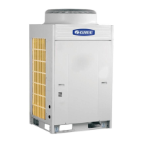
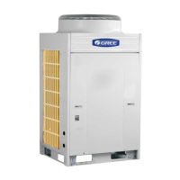
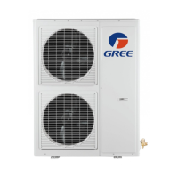
Lists available models with their technical specifications and capacities.
Defines the naming convention and components of the product model for clarity.
Details the various operational functions and features of the air conditioning system.
Provides detailed technical specifications and performance data for each model.
Illustrates the refrigerant piping system for heat pump operations.
Outlines the step-by-step process of unit operation and control sequence.
Explains the core logic behind compressor capacity output and start control mechanisms.
Describes the features and operation of wireless remote controllers.
Details the operation and interface of wired remote controllers.
Explains the functions and operation of the regional control system.
Covers the functions, operation, and display of the smart zone controller.
Details the functions, operation, and display of centralized controllers.
Describes the function and connection of the monitoring software.
Essential safety and procedural considerations before starting installation.
Highlights crucial steps and criteria for successful unit installation.
Visualizes the sequence of steps involved in the installation process.
Provides guidance and cautions for installing the outdoor unit correctly.
Outlines the essential requirements for installing refrigerant piping systems.
Details the specifications for refrigerant pipe diameters and thicknesses.
Specifies the maximum allowable pipe lengths and height differences for optimal performance.
Details the required sizes for gas and liquid connection pipes.
Step-by-step guide for installing the refrigerant piping system.
Visualizes the workflow for installing the refrigerant piping.
Covers the key principles for dry, clean, and airtight refrigerant piping installation.
Instructions for installing metal embedded pipes, including work order.
Guidance on fixing horizontal refrigerant pipes and their supports.
Guidelines for storing and handling refrigerant piping before installation.
General precautions and steps for installing refrigerant piping.
Detailed procedures for welding copper pipes, including safety.
Procedures for cleaning refrigerant piping after welding to remove contaminants.
Procedures for pressure testing and leak detection in the refrigerant piping system.
Guidelines for applying thermal insulation to refrigerant pipes.
Procedures for vacuum pumping to remove air and moisture from the system.
Procedures for calculating and charging the correct amount of refrigerant.
Installation procedures for the condensate drainage system, including testing and insulation.
Crucial points to consider during the installation of condensate pipes.
Procedures for testing condensate pipes for leaks and proper drainage.
Specifies requirements for heat preservation of condensate pipes.
Safety precautions and general guidelines for performing electrical installation tasks.
Details the required specifications for power cords, circuit breakers, and earth leads.
Provides schematic diagrams for indoor/outdoor power and communication line connections.
Explains the function and use of dial-up switches for unit configuration and settings.
Comprehensive list of error codes and their descriptions for unit troubleshooting and diagnosis.
Flowcharts illustrating diagnostic steps for various protection mechanisms and faults.
Illustrates the power flow and distribution within the unit's electrical system.
Details key electrical components and their functions within the power distribution system.
Wiring diagrams showing electrical connections for various unit models.
Step-by-step instructions for disassembling and assembling major unit components.
Provides a detailed list of all unit parts with their codes and quantities for identification.
| Energy Efficiency Ratio (EER) | 3.21 |
|---|---|
| Refrigerant | R410A |
| Power Supply | 380-415V/3Ph/50Hz |
| Outdoor Unit Noise Level | 58 dB(A) |
| Cooling Capacity | 28.0 kW |