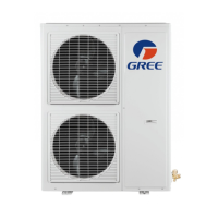
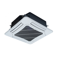
Instruction of the GMV D.C. inverter
12
3). Wrap the pipe with tapes.
(1). Use the adhesive tape to wrap the connecting pipe and cable into one bundle. To prevent
condensate water from overowing out of the drainpipe, the drainpipe shall be separated
from connecting pipe and cable.
(2). Wrap the heat preservation tape so that each ring of tape shall press half of the previous
ring.
(3). Fix the wrapped pipe onto the wall with pipe clamp.
Caution:
① .
Do not wrap the protective tape too tightly, as this will decrease the heat insulation
performance. Ensure that the drain hose of condensate water is separated.
② .
After completing the protection work and wrapping the pipe properly, close the wall holes
with sealing materials.
4.4.7 Connection of Communication Line for Indoor Unit and Outdoor Unit
Open the electrical box of indoor unit and outdoor unit. Insert the distribution line
(communication line) into electrical box via cable hole. Be sure to connect the indoor unit and
outdoor unit in accordance with the wiring diagram labeled on the unit. (Refer to the electrical wiring
of indoor unit and outdoor unit). The specication of power cable shall be selected in reference to
the power capacity and installation environment of the unit. If no error, press wire clip respectively
onto the cables tightly and then reinstall the electrical box cover. Magnetic rings shall be installed
on two ends of the communication line.
Connect communication wire of indoor and outdoor unit by the following
Outdoor unit
CN10
Terminal board Terminal board Terminal board Terminal board
Indoor unit A Indoor unit B Indoor unit N
Wiring
(resistance matching)
Power supply
220-240V ~50Hz
Power supply
220-240V ~50Hz
Power supply
220-240V ~50Hz
Power supply
220-240V ~50Hz
Outdoor unit
Terminal board Terminal board Terminal board Terminal board
Indoor unit A Indoor unit B Indoor unit N
Wiring
(resistance matching)
Power supply
380-415V 3N~ 50Hz
CN20
Power supply
220-240V ~50Hz
Power supply
220-240V ~50Hz
Power supply
220-240V ~50Hz

 Loading...


