MAINTENACE 01140
GMV5 COMPACT MULTI VRF UNIT
SERVICE MANUAL
5.3.2 Operation procedure for the airtightness test
Before ex-factory, cut-off valve for gas pipe and liquid pipe of outdoor unit is turned off. Please confirm that
before operation.
Before test please smear a little corresponding lubricant oil at Blanking plug.and pipe terminal, and use two
wrenches for fixing Blanking plug.
Do not allow to connect the pipeline of outdoor unit for test during airtightness test.
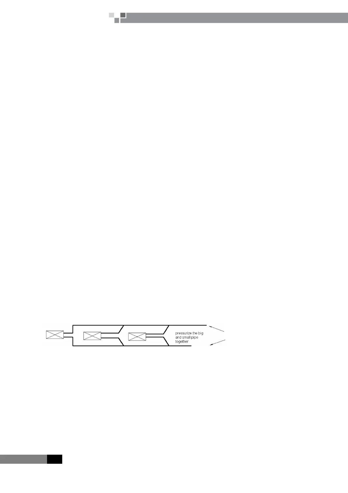
The system test pressure for R410A is 4.15MPa (3.0MPa for R22 refrigerant system). Nitrogen must be used
as the medium for the airtightness test and the nitrogen should be dry. Increase pressure slowly for three steps:
Step 1: Increase pressure slowly to 0.5MPa, stop for 5min and then check the gas leakage. Big leakage may be
found out;
Step 2: Increase pressure slowly to 1.5MPa, stop for 5min to check the airtightness. Small leakage may be
found out;
Step 3: Increase pressure slowly to 4.15MPa for R410A slowly (3.0MPa for R22 refrigerant system), stop for
5min and perform the strength test. Minor leakage or sand hole may be found. Increase pressure to test pressurem,
keep it for 24h and observe whether the pressure is decreasing. If not, the pressure is qualified.
5.3.3 Cautions
a. The test manometer range for R410A should be 4.5MPa above (3.5MPa above for R22 refrigerant system);
b. Record the data on manometerk, ambient temperature and test time at the same time;
c. Pressure modification: when temperature changes 1oC, the temperature will change 0.01MPa
correspondingly.
d. Pressure should be kept the same.
e. If it needs to keep pressure for a long time, decrease the pressire lower than 0.55MPa pr below. Long-time
high pressure can lead to leakage at the welding position, which may cause riskl.
f. Before the airtightness for the pipeline of refrigerant is finished, do not allow to insulate and bundle the
welding positions and connection position of bellmouth of indoor unit.
5.4 Fill and charge refrigerant
5.4.1 Filling procedure of regrigerant
a. Calculate the additional volume of refrigerant
Additional volume of refrigerant R=LA×54 g
LA=L-50 m
L= (12.7 length of liquid pipe) × 2+ (9.52 length of liquid pipe) ×1+ (6.4 length of liquid pipe) ×0.4
When L is less than 50m, no need to add refrigerant
Examples:
 Loading...


