0 1100 CONTROL
GMV5 COMPACT MULTI VRF UNIT
SERVICE MANUAL
temperature sensors, operation state and protection of unit shall be performed to ensure normal and stable operation
of the whole system. Protection codes of outdoor unit shall be displayed on the LED on the main control board
when failure occurs. When drive is at fault, E5 shall be displayed on the display board of indoor unit, and specific
failure type shall be indicated on the LED on the main control board of outdoor unit.
B. Input and output controlled variables
Sensors include ambient temp. sensor, tube-inlet temp. sensor, tube-middle temp. sensor, tube-outlet temp.
sensor, compressor exhaust temp. sensor, compressor casing top temp. sensor, high pressure sensor and low
pressure sensor.
Switch protection: high pressure protection, over-current protection
Output control objects: fan frequency, compressor heat tape (controlled by drive board), compressor AC
contactor (3-phase, controlled by drive board), gas bypass valve, 4-way valve, solenoid valve A, oil equilibrium
valve, liquid bypass valve and capillary solenoid valve.
C. 485 communication interface: indoor unit communication network and adaptor board CN1 shall be
connected to the mainboard of indoor unit through 2-core (3-core pin header) communication cable; drive
communication network and the mainboards CN11~CN14 of outdoor unit shall be connected to the drive board
through 2-core (3-core pin header) communication cable.
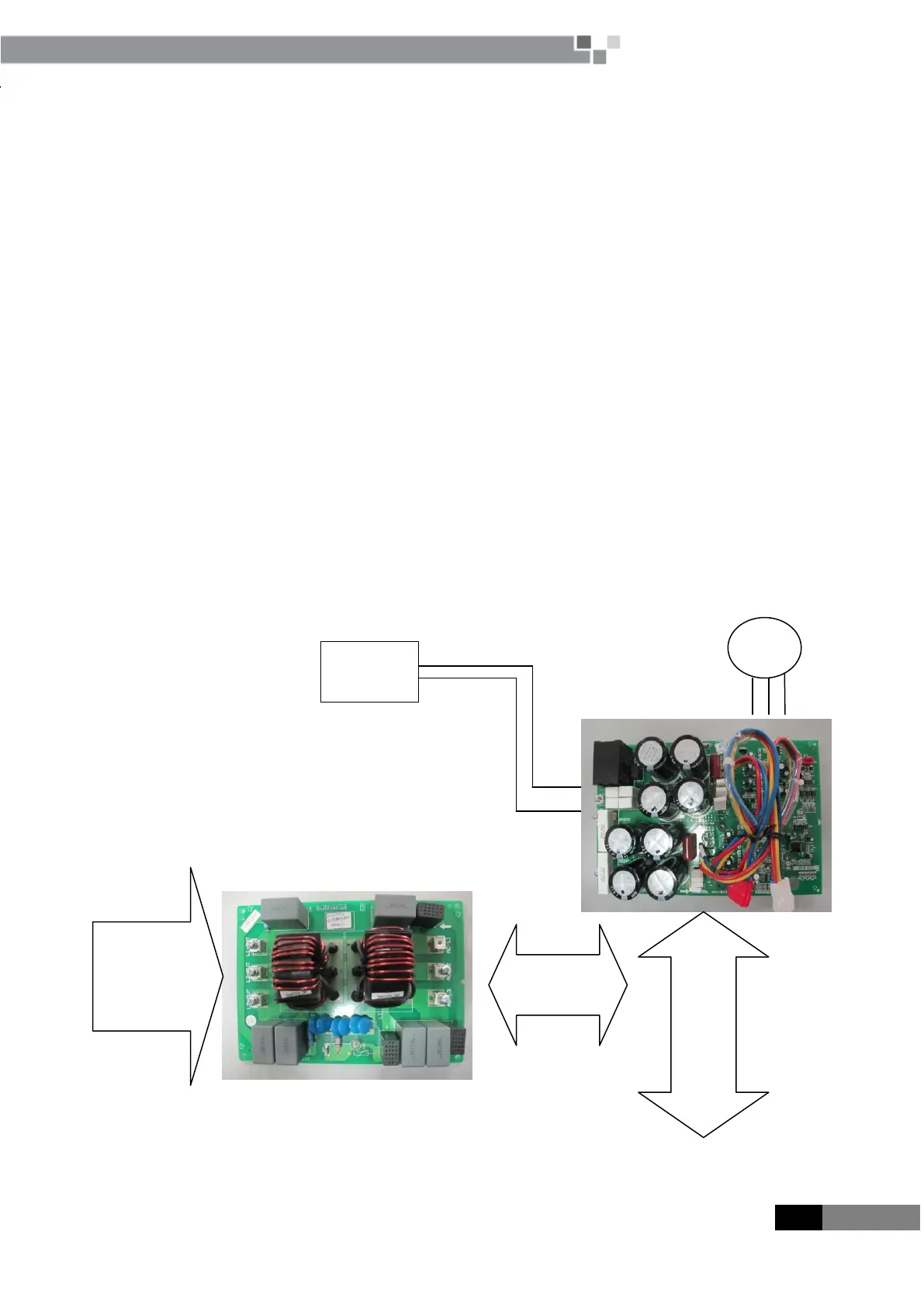
(2)Drive control system
Three-phase power unit:
 Loading...


