Do you have a question about the Gree GPC12AL-K3NNA1A and is the answer not in the manual?
Lists the specific models covered by this service manual and their refrigerant type.
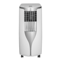
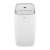
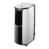
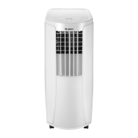
Provides a brief overview of the unit's main features and appearance.
Details technical parameters like capacity, power, dimensions, and operating conditions.
Displays the physical dimensions of the unit for different models.
Illustrates the refrigerant flow and components within the system.
Shows the electrical connections and layout for the unit's components.
Details the component placement and markings on the main and display PCBs.
Explains the functions of buttons and indicators on the unit's control panel.
Describes the buttons, icons, and operation of the remote controller.
Details the safety and protection mechanisms like anti-freeze and over-current.
Crucial safety instructions for installation, maintenance, and handling.
Lists the necessary tools required for servicing the unit.
Outlines the sequence of steps for installing the unit.
Instructions for attaching the wire hook to the unit for cord management.
Procedures for removing condensate water from the unit.
Steps to verify the unit's functionality after installation or servicing.
Lists error codes, their display, and probable causes for diagnosis.
Visual guides to diagnose and resolve specific unit malfunctions.
Provides specific methods for fixing common operational issues.
Visual diagrams showing the assembly breakdown of the unit for different models.
Detailed lists of all part numbers and descriptions for each model.
Steps to detach the front grill, filter, and side panels of the unit.
Procedure for removing the top cover, front panel, and electric box assembly.
Instructions for removing the evaporator, condenser, and compressor.
Provides conversion formulas and tables for temperature readings.
Lists resistance values for temperature sensors at various temperatures.
Provides resistance values for humidity sensors across different temperatures.
| Refrigerant | R410A |
|---|---|
| Weight (Indoor Unit) | 10 kg |
| Net Weight (Indoor Unit) | 10 kg |
| Power Supply | 220-240V, 50Hz |
| Type | Split System |
| Operating Temperature (Cooling) | 18°C to 43°C |
| Cooling Capacity | 12000 BTU/h |