Do you have a question about the Gree GRS-Cm36/NaA-M and is the answer not in the manual?
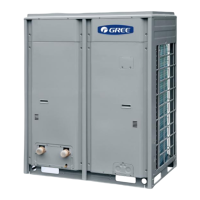
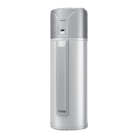
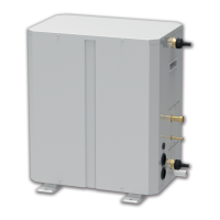
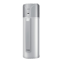
Overview of the product, including its general characteristics and purpose.
Explanation of the fundamental principles governing the operation of the unit.
Key technical specifications and operational parameters of the unit.
Details on additional components or accessories available for the unit.
A step-by-step visual guide outlining the entire installation process.
Essential steps and considerations before commencing the installation procedure.
Guidance on installing the primary water heater unit, including dimensions.
Principles and considerations for designing the water circulation system.
Procedures for installing and insulating water pipes for optimal performance.
Instructions and safety guidelines for the electrical connections of the unit.
Steps for setting up the communication system for unit control and monitoring.
Procedures for safely charging the system with the correct amount of refrigerant.
A flowchart illustrating the steps involved in debugging the unit.
Critical safety precautions that must be observed during operation and maintenance.
Essential steps and tools required before starting the debugging process.
Detailed procedures for operating and testing the unit after installation.
How to configure various functions and settings of the unit for optimal operation.
A list of error codes, their meanings, and troubleshooting logic.
Guidance on diagnosing and resolving common operational issues and errors.
Information on the maintenance and servicing of critical components within the unit.
| Model | GRS-Cm36/NaA-M |
|---|---|
| Category | Water Heater |
| Protection Level | IPX4 |
| Thermostat Range | 30-75 °C |
| Type | Electric Water Heater |
| Capacity | 36L |
| Power Supply | 220V/50Hz |
| Dimensions | 680mm |