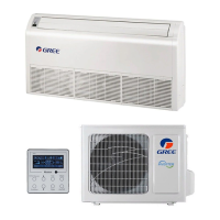
DC Inverter U-match Series Floor Ceiling Type Unit
27
And verify if the pressure gauge at the low pressure side of the manifold valve
assembly reads -1.0Mp (-75cmHg), if not, it indicates there is leak somewhere.
Then, close the switch fully and then stop the vacuum pump.
(6) Wait for 10min to see if the system pressure can remain unchanged. During this
time, the reading of the pressure gauge at the low pressure side can not be
larger than 0.005Mp (0.38cmHg).
(7) Slightly open the liquid valve and let some refrigerant go to the connection pipe
to balance the pressure inside and outside of the connection pipe, so that air will
not come into the connection pipe when removing the hose. Note that the gas
and liquid valve can be opened fully only after the manifold valve assembly is
removed.
(8) Place back the caps of the liquid valve, gas valve and also the service port.
Notice:
For large-size units, there are maintenance ports for liquid valve and gas valve.
During evacuation, you may connect the two hoses of the branch valve assembly to
the maintenance ports to speed up the evacuation.
3.2.4.2 Leak Detection Methods
The following leak detection methods are deemed acceptable for systems
containing flammable refrigerants.
Electronic leak detectors shall be used to detect flammable refrigerants, but the
sensitivity may not be adequate, or may need re-calibration. (Detection equipment
shall be calibrated in a refrigerant-free area).

 Loading...


