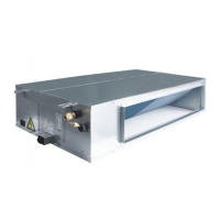
GREE U-Match 6 SERIES UNIT SERVICE MANUAL
11
1.2 Electrical Parameters
Model
Power supply
Circuit breaker
capacity
Min. sectional area of
power cord
V/Ph/Hz A mm
2
GUD35W1/NhA-S
220-240V ~50/60Hz
16 1.5
GUD50W1/NhA-S 16 1.5
GUD71W1/NhA-S 20 2.5
GUD85W1/NhA-S 20 2.5
GUD100W1/NhA-S 32 4.0
GUD125W1/NhA-S 32 4.0
GUD140W1/NhA-S 32 4.0
GUD100W1/NhA-X
380-415V 3N~50/60Hz
16 1.5
GUD125W1/NhA-X 16 1.5
GUD140W1/NhA-X 16 1.5
Model
Power Supply Fuse Capacity
Circuit Breaker
Capacity
Min. Sectional Area of
Power Cord
V/Ph/Hz A A mm
2
Indoor unit 220-240V ~50/60Hz 3.15 6 1.0
NOTICE
:
①
Fuse is located on the main board.
②
Install a circuit breaker near the outdoor units with at least 3mm contact gap. The units must be able
to be plugged or unplugged.
③
Circuit breaker and power cord specifications listed in the above table are determined based on the
maximum power input of the units.
④
Specifications of circuit breaker are based on a working condition where the working temperature is
40°C. If working condition changes, please adjust the specifications according to national standards.
⑤
Adopt 1.0mm² power cords between indoor and outdoor units. The maximum length of 35-85 units is
30m and the maximum length of 100-160 units is 75m. Please select a proper length according to
local conditions. To be in compliance EN 55014, it is necessary to use 8 meters long wire.
⑥
Adopt 2pc of 0.75mm² power cords to be the communication cords between wired controller and
indoor unit. The maximum length is 30m. Please select a proper length according to local conditions.
Communication cords must not be twisted together. To be in compliance with EN 55014, it is
necessary to use 8 meters long wire.
⑦
The wire gauge of communication cord should not be less than 0.75mm². It’s recommended to use
0.75mm² power cords as the communication cords.

 Loading...


