13
Technical Information
Service Manual
5. Electrical Part
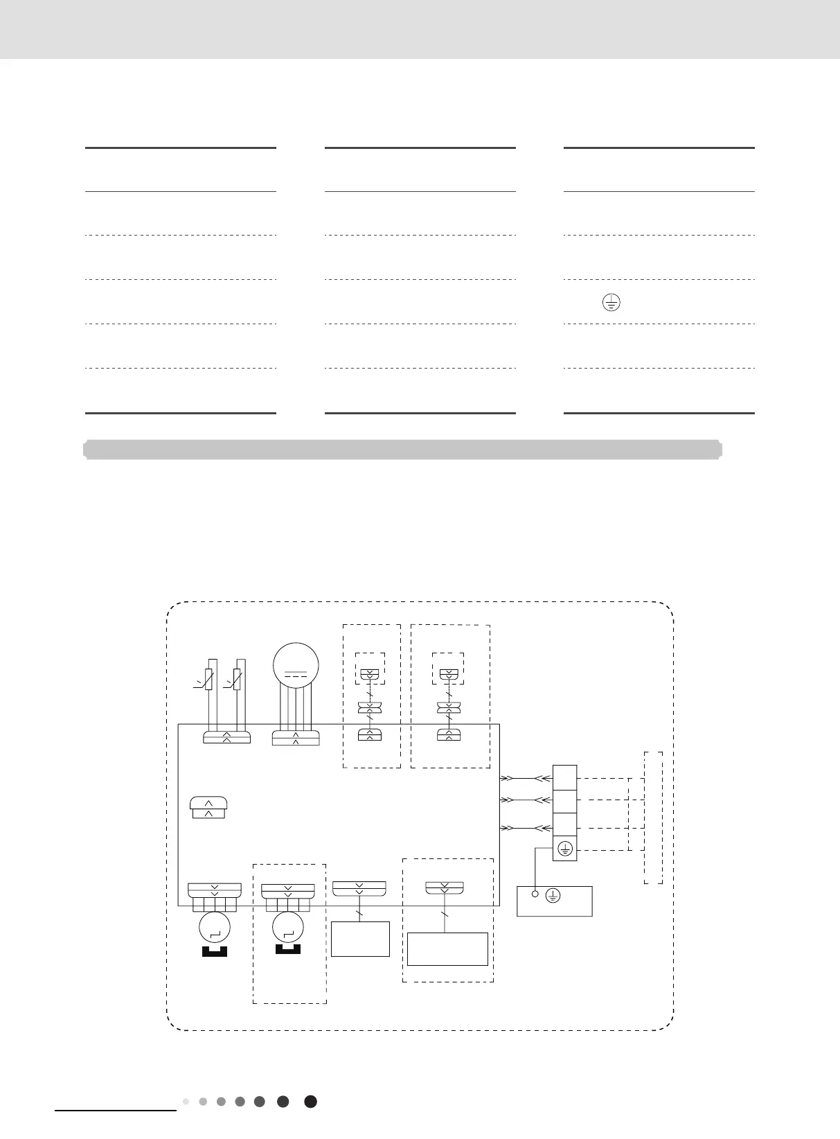
5.1 Wiring Diagram
● Indoor Unit
●Instruction
Symbol Symbol Color Symbol Symbol Color Symbol Name
WH White GN Green CAP Jumper cap
YE Yellow BN Brown COMP Compressor
RD Red BU Blue Grounding wire
YEGN Yellow/Green BK Black / /
VT Violet OG Orange / /
Note: Jumper cap is used to determine fan speed and the swing angle of horizontal lover for this model.
600007067048
GWC12ATCXB-K6DNA1B/I
LEFT-RIGHT
MOTOR
STEPPING
MOTOR
STEPPING
AP1
RECEIVER AND
DISPLAY BOARD
DISPLAY
TUBE
AP2
PRINTED CIRCUIT BOARD
JUMP
CAP
M3
SWING-LR
SWING-UD
M2
OPTIONAL
(SWING-UD1)
T-SENSOR
TEMP.
SENSOR
RT2
ROOM
COM-MANUAL
AP3
WIRED
CONTROLLER
DOOR-C
(DRY-C)
OPTIONAL
AP4
OPTIONAL
GATECONTROL
TEMP.
SENSOR
FAN
MOTOR
RT1
0
0
DISP
(DRYCONTACT)
COM-OUT
AC-L
N(N1)
BU
BK
YEGN
2
N(1)
OUTDOOR UNIT
3
BN
BU
BK
BN
CABLE
CONNECTING
BLOCK
TERMINAL
EVAPORATOR
PE
XT
YEGN
HEALTH
OPTIONAL
ION
GENERATOR
M1
DC-MOTOR
 Loading...