142
Installation and Maintenance
Service Manual
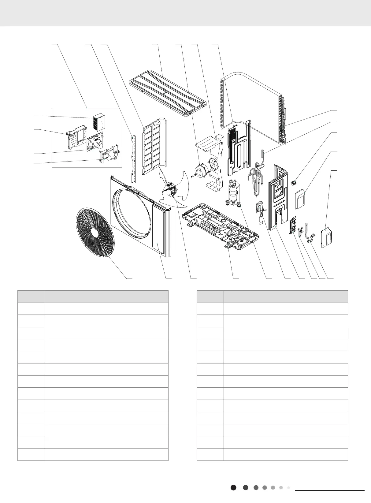
The component is only for rererence;please refer to the actual product
GWH24AFE-K6DNA2I/O
1 2 3 4 5 6 7 8 9 10
12
13
14
15
16171819202122
23
24
25
26
11
NO. Description
1 Front Grill
2 Front Panel
3 Axial Flow Fan
4 Chassis Sub-assy
5 Compressor and Fittings
6 Electronic Expansion Valve
7 Right Side Plate
8 Valve Support
9 Cut-off valve 1/4(N)
10 Cut-off valve 5/8(N)
11 Valve Cover
12 Handle
13 Terminal Board
NO. Description
14 4-Way Valve Assy
15 Condenser Assy
16 Clapboard Assy
17 Motor Support
18 Brushless DC Motor
19 Top Cover Assy
20 Left Side Plate
21 Condenser Left Border Plate
22 Electric Box Assy
23 Radiator
24 Electric Box
25 Main Board
26 Electric Box Cover
Some models may not contain some parts, please refer to the actual product.
 Loading...