GREE Air-ccoled Closed Control Unit Service Manual
119
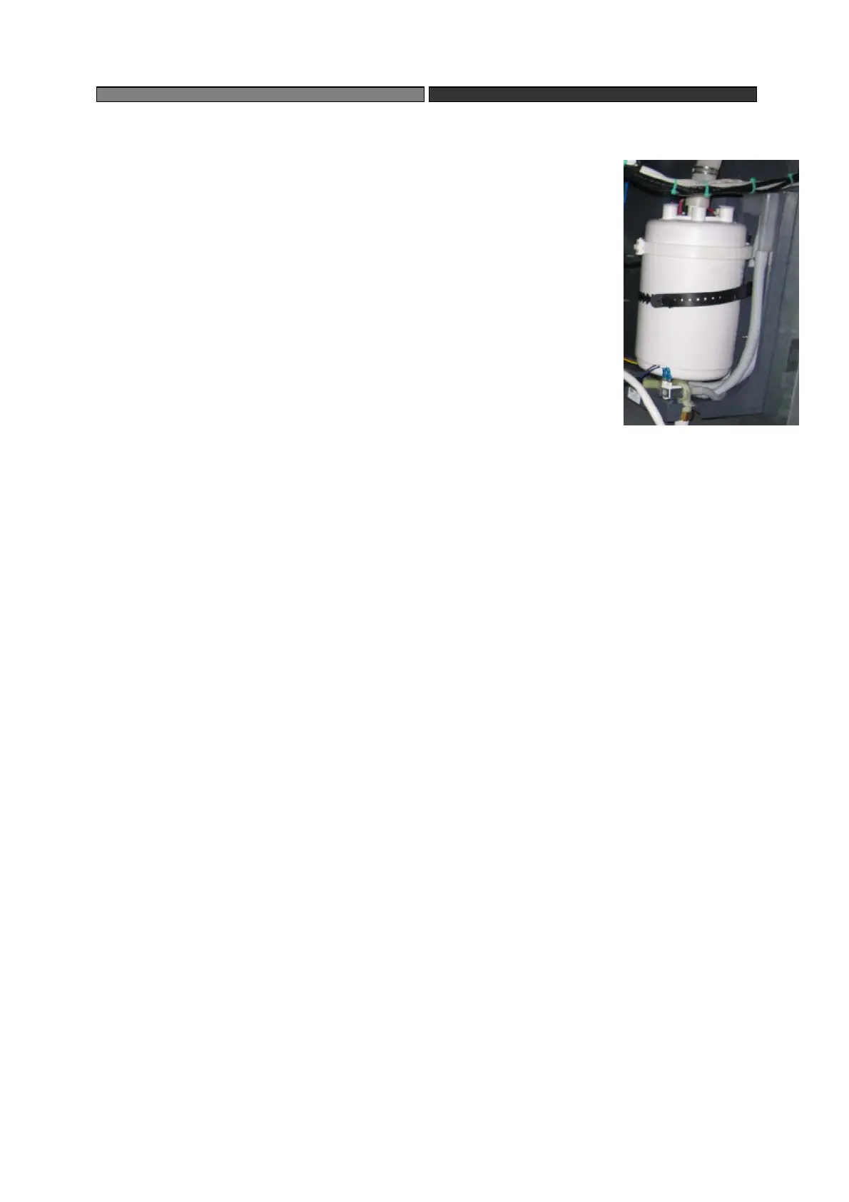
5.2.3 Humidifier
Humidifier Consists of three main parts: humidifying tank, discharge,
valve and feed valve
(1)Replace humidifying tank:
Disassembly steps:
◆Catch joint of electrode and push it downward for 2mm along
the steam
cylinder.
◆Loosen clamp of humidifying tank and open its cover;
◆Remove the electrode;
◆Remove O type joint ring of electrode
Assembly steps:
Assemle the humidifier based on the reverse steps of the disassembly.
Note:
◆Before assembly of humidifying tank, check the O type joint ring. If it is damaged, replace
it;
◆Place the O type joint ring on electrode and insert the electrode into the cover of
humidifying tank. Make sure the joint is locked;
◆Place the humidifying cover on proper position and fix it with clamp;
◆Place the humidifying tank on retaining device on both sides or the rear. Push the tank
downward along the discharge vavle until it can’t be pushed anymore.
(2)Replace discharge valve
Before removal of discharge valve, remove dehumidifying tank firstly. The steps are as
follows:
◆ Remove cable;
◆ Loosen hose clamp and remove water-in hose;
◆Remove 2 retaining screws and discharge valve;
◆Disassembly of discharge valve: firstly remove nut A and then coil B. Catch retaining ring
C and remove valve D vertically. Then separate the ring from valve.
The steps of assembly of discharge valve are reverse steps of disassembly.
(3)Replace feed valve:
Before removal of feed valve, remove humidifying tank firstly. The steps are as follows:
◆Remove cable;
◆Loosen hose clamp and separate water-in hose;
◆Remove water–in nut.
◆Remove 2 retaining screws and discharge vavle.
Assembly of feed valve are reverse steps above.
 Loading...