10
Technical Information
Service Manual
1
1
23 4 5 6 7 8 9 10
11
12
13
14
15
16
Ɣ
BOTTOM VIEW
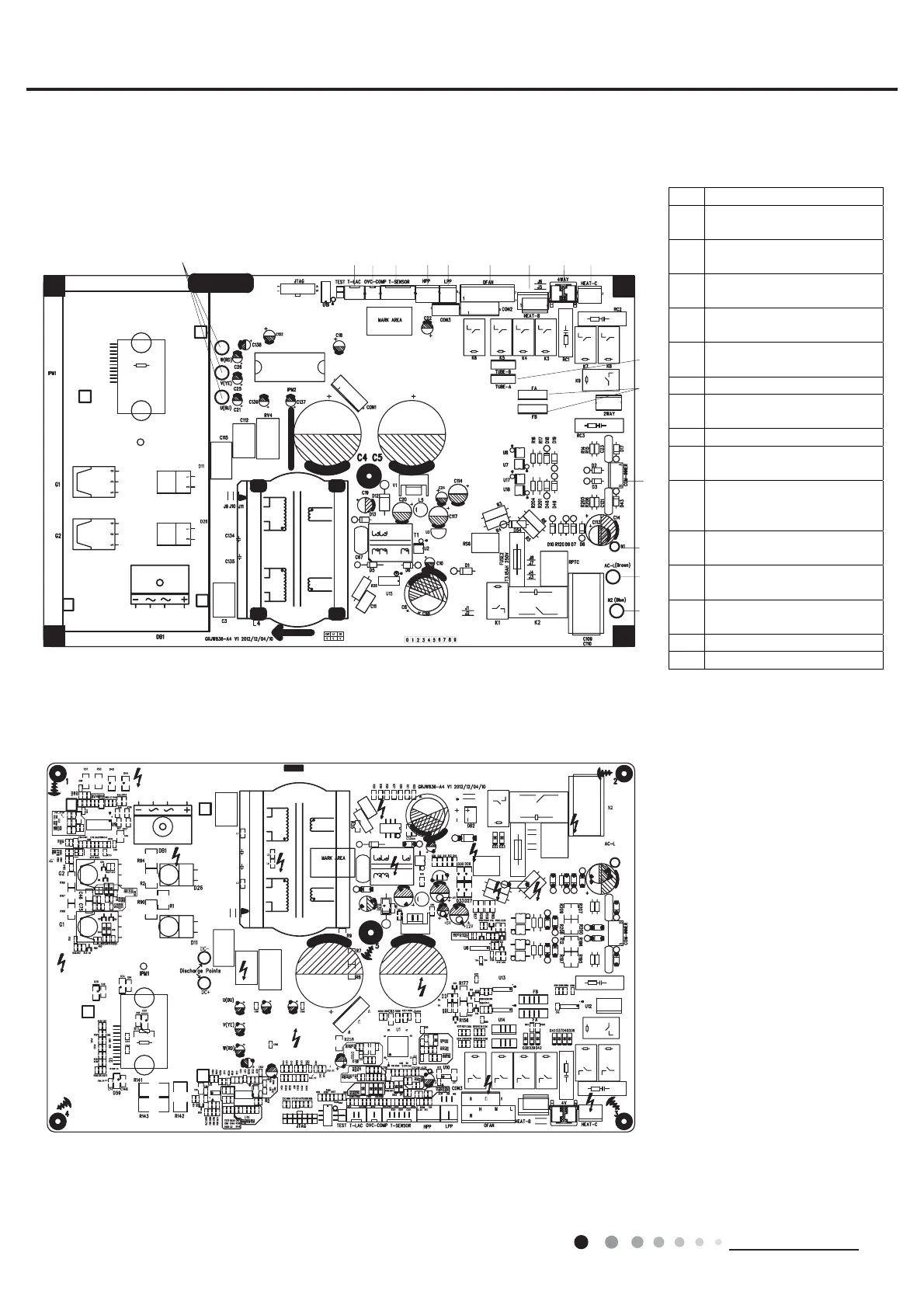
5.2 PCB Printed Diagram
MULTI18HP230V1CO
Ɣ
TOP VIEW
1 Terminal of compressor
2
Terminal of low-temperature
cooling temperature sensor
3
Overload protection terminal of
compressor
4
Temperature sensor terminal of
outdoor unit
5
High pressure protection
terminal
6
Low pressure protection
terminal
7 Terminal of outdoor unit
8
Electric heating belt terminal of
chassis
9 Terminal of 4-way valve
10
Electric heating belt terminal of
compressor
11
Terminal of temperature sensor
wire for liquid valve and gas
valve
12
Terminal of electronic
expansion valve
13
Terminal of communication wire
for indoor unit and outdoor unit
14
Neutral wire terminal for
communication
15 Live wire terminal
16 Neutral wire terminal
 Loading...