

K
Kelly JohnsonAug 22, 2025
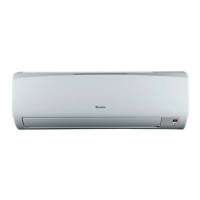
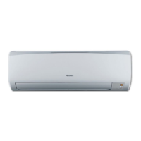
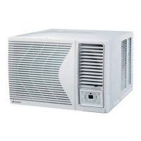
How to check voltage measurements for Gree Air Conditioner Indoor Fan Motor?
- TTina JohnsonAug 23, 2025
To troubleshoot out-of-range resistance measurements in the Indoor Fan Motor of your Gree Air Conditioner, ensure the power is off with the ‘PG’ connector removed. Then, check the voltage measurements against the provided charts.