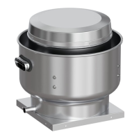
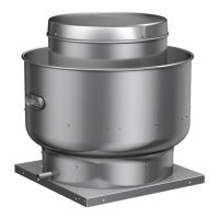
Upblast Centrifugal Roof Exhaust4
Installation
General Ventilation Installation
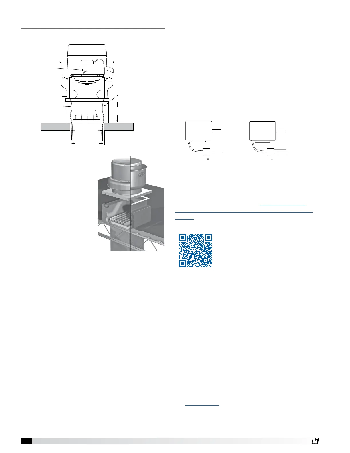
Figure 4 - Typical Roof Mounting Installation
Recommended
Duct and Damper
Size
Roof Deck
Damper
Recommended
Roof Opening
Power Wiring
by Others
8 inch minimum
(203 mm)
Factory Wired
Motor to
Junction Box
Control Wiring
1. On the roof surface,
cut an appropriately
sized hole and follow
manufacturer’s
instructions on curb
installation. Caulk and
flash the curb to ensure
a water tight seal.
2. If unit is equipped with
a backdraft damper, it
should be installed now.
3. To access the motor
compartment for sizes
smaller than 300, press
two adjacent push-
pin toolless fasteners simultaneously and pull
the motor cover away. For sizes 300 and above,
remove the screws.
4a. On belt drive fans, use the lifting points or lifting
lugs on the drive frame or bearing plate to lift and
place the unit on top of roof curb. Refer to Figure 1
and 2, page 2.
4b. On direct drive fans, lift and place the unit on top
of roof curb using the lifting points or hooks under
the horizontal supports. Refer to Figure 1 and 2,
page 2.
5. Secure fan to curb using a minimum of eight lag
screws, metal screws or other suitable fasteners.
Shims may be required depending upon curb
installation and roofing material.
6. Verify power line wiring is de-energized before
connecting fan motor to power source.
7. For commercial kitchen and UL Listed emergency
smoke control applications, the electrical supply
must enter the motor compartment through
the breather tube. For other non-flammable
applications, the electrical supply can be routed
through the conduit chase between the curb cap
and the bottom of the motor compartment.
Figure 5 - Roof Curb Installation
Figure 6 - Typical Wiring Diagram
MOTOR
L1
115/208-230/60/1
208-230/460/60/3
MOTOR
J-BOX
J-BOX
SUPPLY VOLTAGE
SUPPLY VOLT
L2
L1
L2
L3
8. Connect power supply wiring to the motor as
indicated on the motor nameplate or terminal box
cover. Check the power source for compatibility
with the requirements of your equipment.
9. Check fan wheel for free rotation, recenter if
necessary. Check setscrew(s) for tightness.
10. Check all fasteners for tightness.
11. Mount and wire safety disconnect switch under
motor cover. Wire control switches at ground level,
refer to Figure 6.
12. Replace motor cover.
Vari-Green
®
Wiring
For Vari-Green wiring refer to the Vari-Green Motor
and Controls Installation, Operation and Maintenance
Manual for complete wiring and operation instructions.
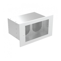
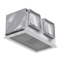
1a. Curb: Cut an appropriate sized hole in the wall for
either through wall (recommended) or exterior face
mount and follow the manufacturer’s instructions on
curb installation.
1b. Wall bracket: Cut an appropriate sized hole in the
wall for exterior face mounting. If unit is equipped
with a backdraft damper, it should be installed in
the ductwork/wall opening now.
Sidewall Mounting Installation