Do you have a question about the Greenheck EDD-401 and is the answer not in the manual?
This document outlines the installation, operation, and maintenance procedures for a splice angle, an essential component designed to connect sections of a larger system, likely a louver or damper assembly, to ensure structural integrity and proper alignment. The primary function of the splice angle is to provide a robust mechanical connection between two adjacent sections, effectively extending the overall length or height of the assembly while maintaining its structural rigidity. This is crucial for applications where the complete system cannot be manufactured or transported as a single unit due to size constraints, necessitating modular construction.
The installation process is straightforward, emphasizing precision and adherence to specific steps to ensure optimal performance and longevity. The first step involves attaching a 36-inch angle splice to the lower section of the assembly. This attachment is critical, as the splice angle must be positioned with 18 inches extending above the lower section. This specific placement is not arbitrary; it ensures that there is sufficient overlap and surface area for the subsequent connection to the upper section, thereby distributing stress evenly across the joint and preventing localized points of failure. The "TOP VIEW" diagram provided in the manual serves as a visual guide for correctly orienting the angle splice, which is vital for installers to avoid errors that could compromise the structural integrity of the final assembly.
Following the initial attachment, the second step focuses on preparing the support angles for the connection. This involves drilling 3/8-inch holes into the support angle on both the upper and lower sections. The critical aspect here is that these holes must precisely match the pre-drilled holes in the 36-inch splice angle. This alignment is paramount for a secure and flush fit, ensuring that the bolts can pass through without obstruction and that the sections are pulled together tightly. Any misalignment at this stage could lead to difficulties in assembly, potential damage to the components, or, more critically, a weakened joint that could fail under operational stress. The use of a specific drill bit size (3/8 inch) indicates the precise engineering tolerances required for this connection.
The third and final step in the installation process is the actual attachment of the splice angle using 5/16-inch bolts. The manual specifies that six bolts are required per splice angle. This quantity is determined by engineering calculations to provide adequate fastening strength for the intended application. The choice of 5/16-inch bolts, along with the specified number, ensures that the joint can withstand the various forces it will encounter during operation, including wind loads, vibration, and the static weight of the assembly itself. The bolts, along with their corresponding nuts and washers, are crucial for creating a rigid and permanent connection. The manual also includes a note to reference the Alignment Plate IOM if alignment plates are to be field installed, indicating that some configurations may require additional components to ensure perfect alignment, especially in larger or more complex installations.
The components supplied by Greenheck for this installation are carefully selected to ensure durability and reliability. These include 5/16-18x1 HH ZP CS fasteners (part number 025), which are likely hex head zinc-plated cap screws, offering good corrosion resistance and strength. The 5/16-ZP Spin-Lock Nut (part number 456) is designed to resist loosening due to vibration, a common issue in HVAC and ventilation systems, thereby maintaining the integrity of the joint over time. Additionally, #10-16 x3/4 TPH 18-8 SS fasteners (part number 108) are included, which are likely self-tapping screws made of 18-8 stainless steel, providing excellent corrosion resistance and strength for specific attachment points, possibly for the alignment plates or other ancillary components. The inclusion of these specific fasteners highlights Greenheck's commitment to providing a complete and robust solution.
The "TOP VIEW" diagram provides a detailed visual representation of the assembly, illustrating the relationship between the 36-inch angle splice (part number 507859), which is field applied, and the 1.5-inch aluminum support angle (0.125-inch thickness), which is shop applied. This distinction between field-applied and shop-applied components is important for understanding the installation sequence and the division of labor. The shop-applied components are pre-installed at the factory, ensuring a high degree of precision and quality control, while the field-applied components are installed on-site, allowing for flexibility during assembly. The diagram also shows the placement of the fasteners (025, 456, 108) and indicates the "UIF" (User Installed Fastener) locations, guiding the installer on where to apply the supplied hardware. The presence of an "ALIGNMENT PLATE" in the diagram, even if optional, underscores the importance of precise alignment for the overall system's performance.
The "ACTUAL SECTION/SHIP SIZE" label in the diagram suggests that the splice angle is designed to accommodate various section sizes, making it a versatile component for different louver or damper models. This modularity is a key feature, allowing manufacturers to produce standardized sections that can be combined in various configurations to meet diverse project requirements, reducing custom fabrication costs and lead times.
Maintenance features, while not explicitly detailed as a separate section, are implicitly addressed through the robust design and choice of materials. The use of zinc-plated and stainless steel fasteners provides inherent corrosion resistance, which is crucial for components exposed to varying environmental conditions, especially in outdoor or industrial settings. The spin-lock nuts are a passive maintenance feature, as they reduce the likelihood of fasteners loosening over time, thereby minimizing the need for periodic re-tightening. Regular visual inspections of the bolted connections for any signs of loosening, corrosion, or damage would be a recommended maintenance practice, although not explicitly stated in this particular excerpt. Any signs of wear or damage to the splice angle or fasteners would necessitate replacement to maintain the structural integrity of the assembly.
In summary, the splice angle is a critical structural component for modular louver and damper systems, enabling the assembly of larger units from smaller, manageable sections. Its function is to provide a strong, rigid, and precisely aligned connection between these sections. The installation process is designed to be straightforward yet requires careful attention to detail, particularly regarding measurement, drilling, and fastener application, to ensure optimal performance and longevity. The use of high-quality, corrosion-resistant fasteners and the modular design contribute to the system's overall reliability and ease of use, while implicit maintenance considerations revolve around the durability of the chosen materials and the secure fastening methods employed.
| Model | EDD-401 |
|---|---|
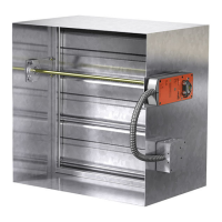
| Category | Fire and Smoke Dampers |
| Static Pressure Range | Up to 4 in. wg |
| Construction | Galvanized Steel |
| Actuator Voltage | 24V AC/DC |
| Blade Type | Parallel |
| UL Classification | UL 555S |
| Approvals | UL |
| Type | Dynamic Fire and Smoke Damper |
| Temperature Rating | 350°F (177°C) |