EasyManua.ls Logo

Greenheck ESD-202 - User Manual

Greenheck ESD-202
10 pages
Print Icon
To Next Page IconTo Next Page
Loading...
®
Stationary, Drainable Blade Louver Models 1
®
Document 485608
Stationary, Drainable Blade Louvers
Models ESD-202, ESD-403, ESD-435, ESD-603 and ESD-635
Installation, Operation and Maintenance Manual
Please read and save these instructions for future reference. Read carefully before attempting to assemble, install,
operate or maintain the product described. Protect yourself and others by observing all safety information. Failure
to comply with these instructions will result in voiding of the product warranty and may result in personal injury
and/or property damage.
Receiving and Handling
Upon receiving louvers, check for both obvious
and hidden damage. If damage is found, record all
necessary information on the bill of lading and file
a claim with the final carrier. Check to be sure that
all parts of the shipment, including accessories are
accounted for.
Safety Warning
Improper installation, adjustment, alteration, service
or maintenance can cause property damage, injury
or death. Read the installation, operating, and
maintenance instructions thoroughly before installing
or servicing this equipment.
Table of Contents
General Louver Installation Instructions . . . . . . . . 2
Single Section Wide x Single Section High Installation 3
Single Section Wide x Multi Section High Installation. 4
Multi Section Structural Support Tables . . . . . . . . 5
Multi Wide x Single Section High - Unsupported . . . 6
Multi Wide x Single Section High - Supported . . . . 7
Multi Section Wide x Multi Section High Installation . 8
Question and Answer IconNeed help?

Do you have a question about the Greenheck ESD-202 and is the answer not in the manual?

Overview

This document provides comprehensive instructions for the installation, operation, and maintenance of Greenheck Stationary, Drainable Blade Louvers, specifically models ESD-202, ESD-403, ESD-435, ESD-603, and ESD-635. It emphasizes safety precautions and proper handling to ensure product longevity and prevent damage or injury.

Function Description

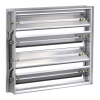
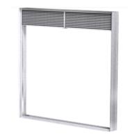
The Greenheck Stationary, Drainable Blade Louvers are designed to provide ventilation and weather protection for building openings. Their primary function is to allow air to pass through while preventing the ingress of rain and other elements. The drainable blade design helps to channel water away from the building envelope, ensuring a dry interior. These louvers are suitable for various applications where controlled airflow and weather resistance are critical. They are engineered to withstand specific wind loads, with structural support requirements varying based on the louver's width and height.

Usage Features

The installation process for these louvers is detailed, covering both single and multiple section configurations, as well as scenarios requiring additional structural support.

Receiving and Handling:

Upon delivery, it is crucial to inspect the louvers for any visible or hidden damage. Any damage should be documented on the bill of lading, and a claim should be filed with the carrier. All parts and accessories included in the shipment must be accounted for. When handling louver sections, extreme care is advised to prevent damage. Louvers should be lifted by their frame or designated supports, using multiple lifting points to avoid deformation. It is explicitly stated: DO NOT LIFT LOUVERS BY THE LOUVER BLADES to prevent damage to the louver finish.

Installation Instructions:

  1. Preparation: All crates, boxes, and cartons should be located. Louvers and accessories should be removed from packaging and inspected for damage. Dimensions must be verified, and all required pieces must be present.
  2. Section Types: Single-section louvers ship fully assembled. Multiple-section assemblies ship as individual sections and are combined on-site. Large multiple-section assemblies may arrive in multiple crates.
  3. Identification: Each louver section has a factory-applied label indicating its size and a Tag identification if provided during the order process.
  4. Hardware and Opening Inspection: All necessary installation hardware, including mounting angles and fasteners (either customer-provided or optional manufacturer-provided), must be available. The opening itself should be inspected for any damage, obstructions, or debris that might affect installation. These must be removed, and adequate substrate depth verified.
  5. Fit Verification: The dimensions of the opening should be checked to ensure the louver will fit correctly, and the opening must be square and plumb.

Single Section Wide x Single Section High Installation:

  1. Sill Placement: If provided, the optional extended sill is placed in the opening.
  2. Mounting Hardware: Mounting angles and fasteners are located. Clip angles and fasteners are typically provided by others unless optional mounting angles were ordered from the manufacturer. Anchors to the structure are also by others.
  3. Louver Placement: The louver is placed in the opening and shimmed around the perimeter to ensure proper spacing for backer rod and caulk joint.
  4. Securing Louver: Appropriate fasteners are used to secure the mounting angles to the back of the louver frame at the perimeter.
  5. Leveling and Anchoring: The louver must be level and correctly positioned within the opening. The mounting angles are then secured to the structure using the appropriate anchors for the building substrate material.
  6. Sealing: Once secured, backer rod and caulk are installed around the perimeter of the opening at the front of the louver.

Single Section Wide x Multiple Section High Installation:

This configuration involves connecting upper and lower louver sections.

  1. Alignment Plates: Shipped loose alignment plates for the jambs are used to connect upper and lower louver sections according to their specific instructions.
  2. Blade Support Angle (if required): If sections are wide enough to need a blade support angle, the upper and lower section angles must be spliced using a shipped loose Splice Angle kit.
  3. Sill and Mounting Hardware: Similar to single-section installation, the extended sill (if provided) is placed, and mounting angles and fasteners are located.
  4. Louver Placement and Securing: The louver is placed in the opening, shimmed, and secured to the structure using fasteners and anchors, ensuring it is level and correctly positioned.
  5. Sealing: Backer rod and caulk are installed around the perimeter of the opening.

Multiple Section Wide x Single Section High Installation - Unsupported:

This applies when multiple louver sections are installed side-by-side without additional structural support.

  1. Sill and Mounting Hardware: Similar initial steps as above.
  2. Left Section Placement: The leftmost louver section (as viewed from the exterior) is placed in the opening and shimmed.
  3. Securing Left Section: Mounting angles are secured to the louver frame and then to the structure, ensuring the louver is level.
  4. Subsequent Sections: The next louver section to the right is placed, and steps 3-5 are repeated for all additional sections.
  5. Sealing: Backer rod and caulk are installed around the perimeter and at the mullion joint between louver jambs.

Multiple Section Wide x Single Section High Installation - Supported:

This configuration requires additional structural support for wider openings.

  1. Sill and Mounting Hardware: Similar initial steps.
  2. Left Section Placement and Securing: The leftmost louver section is placed, shimmed, and secured to the structure.
  3. Subsequent Sections: Additional sections are placed and secured.
  4. Structural Supports: Additional structural supports (not provided by the manufacturer) are installed at the vertical louver mullions. The louver frame is then secured to these supports using appropriate mounting angles and/or anchors.
  5. Sealing: Backer rod and caulk are installed around the perimeter and at the mullion joint.

Multiple Section Wide x Multiple Section High Installation:

This involves field assembly of multiple louver sections to create a large opening.

  1. Alignment Plates: Shipped loose alignment plates are used to connect upper and lower louver sections.
  2. Blade Support Angle (if required): If sections are wide enough, blade support angles are spliced using the Splice Angle kit.
  3. Sill and Mounting Hardware: Similar initial steps.
  4. Combined Left Section Placement: The combined left louver section assembly is placed in the opening, shimmed, and secured to the structure.
  5. Subsequent Combined Sections: The next combined louver section to the right is placed, and steps 6-7 are repeated for all additional sections.
  6. Structural Supports: Additional structural supports (not designed or provided by the manufacturer) may be required behind the louver mullions. The louvers must be secured to these supports.
  7. Sealing: Backer rod and caulk are installed around the perimeter of the opening.

Maintenance Features

The manual emphasizes proper installation and handling to ensure the long-term performance and integrity of the louvers. While specific routine maintenance steps are not explicitly detailed in the provided excerpts, the focus on correct installation procedures inherently contributes to reduced maintenance needs. The use of sealants and backer rods during installation is crucial for weatherproofing, which is a key aspect of preventing future maintenance issues related to water ingress.

The document also highlights the importance of reading the installation, operating, and maintenance instructions thoroughly before installing or servicing the equipment. This implies that adherence to these guidelines is a form of preventative maintenance, ensuring the device operates as intended and avoids premature wear or failure. The warranty information, available online, likely outlines conditions related to proper installation and maintenance for warranty validity.

In summary, the Greenheck Stationary, Drainable Blade Louvers are designed for effective ventilation and weather protection. Their usage involves careful handling and precise installation, with detailed instructions provided for various configurations. Proper installation, including sealing and structural support where necessary, is paramount for their performance and to minimize future maintenance requirements.
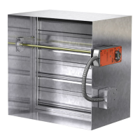
Greenheck ESD-202 Specifications

General IconGeneral
ConstructionGalvanized steel
UL 555 Fire Resistance Rating1.5 hours
Maximum Velocity2000 fpm
Maximum Pressure4 in. wg
UL 555S Leakage ClassClass I or Class II

Related product manuals