®
Multi-Blade Fire and Combination Fire Smoke Dampers 1
Document 481318
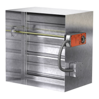
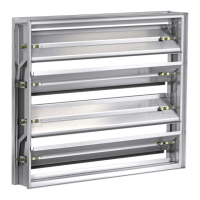
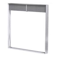
Mult-Blade Fire and Combination
Fire Smoke Damper
DFD-xxx, DFDAF-xxx, FSD-xxx, FSD-xxxV, SEDFD-xxx,
SEFSD-xxx and SSFSD-xxx
1
1
⁄2 and 3 Hour Fire and Combination Fire Smoke Dampers
Installation, Operation and Maintenance Manual
Please read and save these instructions for future reference. Read carefully before attempting to assemble, install,
operate or maintain the product described. Protect yourself and others by observing all safety information. Failure
to comply with these instructions will result in voiding of the product warranty and may result in personal injury
and/or property damage.
Receiving and Handling
Upon receiving dampers, check for both obvious
and hidden damage. If damage is found, record all
necessary information on the bill of lading and file
a claim with the final carrier. Check to be sure that
all parts of the shipment, including accessories, are
accounted for.
Dampers must be kept dry and clean. Indoor storage
and protection from dirt, dust, and the weather is
highly recommended. Do not store at temperatures in
excess of 100°F (38°C).
SAFETY WARNING
Improper installation, adjustment, alteration, service
or maintenance can cause property damage, injury
or death. Read the installation, operating, and
maintenance instructions thoroughly before installing
or servicing this equipment.
These instructions apply to 1
1
⁄2 and 3 hour rated
fire and combination fire smoke dampers mounted
in: 1) masonry, block, or stud walls and 2) concrete
floors. Specific requirements in these instructions are
mandatory. Dampers must be installed in accordance
with these instructions to meet the requirements of UL
555 and/or UL 555S.
Note: Combination fire smoke and fire dampers
are manufactured and labeled for either vertical or
horizontal installation. The dampers must be installed in
accordance with labeling.
Table of Contents
General Information . . . . . . . . . . . . . . . . . . 2
Electrical Guidelines . . . . . . . . . . . . . . . . . . 2
Pre-Installation Guidelines . . . . . . . . . . . . . . . 2
Preparation of Openings . . . . . . . . . . . . . . . . 3
Clearances Required Between Damper Sleeves & Wall/
Floor Openings. . . . . . . . . . . . . . . . . . . . . 4
Installing Multiple Section Damper Assemblies . . . . 4
Multiple Section Damper Wiring . . . . . . . . . . . . 5
Maximum Assembly Tables . . . . . . . . . . . . . . 5
Inserting Damper into Wall/Floor Openings . . . . . . 6
Securing the Damper/Sleeve Assembly to Wall/Floor
Openings . . . . . . . . . . . . . . . . . . . . . . . . 6
Duct to Sleeve Connection . . . . . . . . . . . . . . 8
Actuator and Temperature Response Device
Connections . . . . . . . . . . . . . . . . . . . . . .11
Damper Commissioning and Periodic Testing. . . . .12
Damper Maintenance . . . . . . . . . . . . . . . . .12
Damper Troubleshooting. . . . . . . . . . . . . . . .12