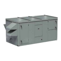
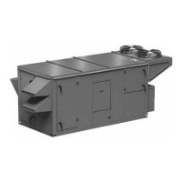
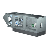
General Description - NOT model specificEnergy Recovery Ventilator with Heating and Cooling
14
1 Fan
Wheel
Dia.
1 Fan
Wheel
Dia.
R
o
t
a
t
i
o
n
R
o
t
a
t
i
o
n
R
o
t
a
t
i
o
n
R
o
t
a
t
i
o
n
Length of Straight Duct
GOOD
POOR
GOODPOOR
GOOD
POOR
Tu rning
Vanes
Tu rning
Vanes
SYSTEM EFFECT FACTOR CURVES
FPM X 100
OUTLET VELOCITY
0 5 10 15 20 25 30 35 40 45
1.2
1.0
0.8
0.6
0.4
0.2
0.0
STATIC PRESSURE LOSS
CURVE 1
CURVE 2
CURVE 3
CURVE 4
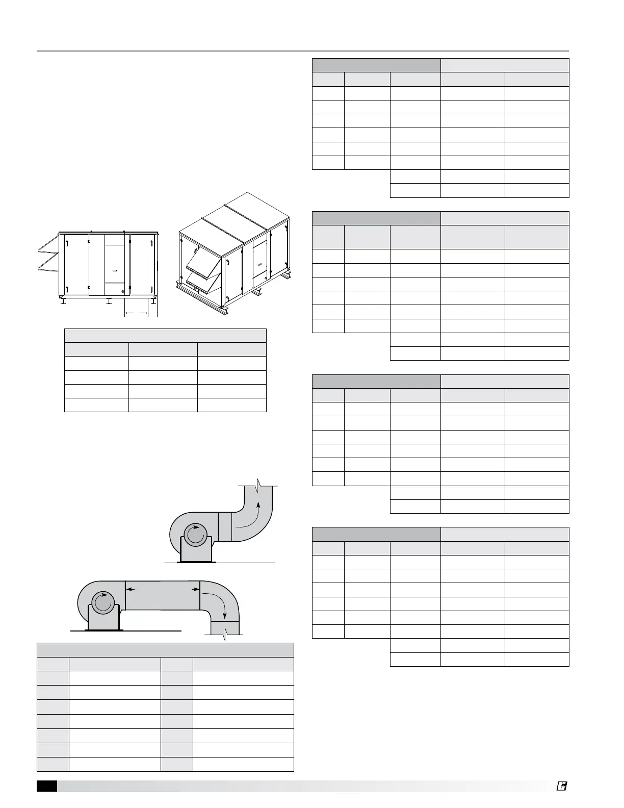
Ductwork Connections
Examples of poor and good fan-to-duct connections
are shown. Airflow out of the fan should
be directed straight or curve the
same direction as the
fan wheel rotates. Poor
duct installation will result
in low airflow and other
system effects.
1 Fan
Wheel
Dia.
1 Fan
Wheel
Dia.
R
o
t
a
t
i
o
n
R
o
t
a
t
i
o
n
R
o
t
a
t
i
o
n
R
o
t
a
t
i
o
n
Length of Straight Duct
GOOD
POOR
GOODPOOR
GOOD
POOR
Tu rning
Vanes
Tu rning
Vanes
SYSTEM EFFECT FACTOR CURVES
FPM X 100
OUTLET VELOCITY
0 5 10 15 20 25 30 35 40 45
1.2
1.0
0.8
0.6
0.4
0.2
0.0
STATIC PRESSURE LOSS
CURVE 1
CURVE 2
CURVE 3
CURVE 4
ERCH-20 Recommended Duct Size
Intake Duct Size Discharge 9-9 Blower 10-6 Blower
OIE 22 x 26 SDE 16 x 16 16 x 16
OIT 24 x 20 SDS 16 x 16 16 x 16
RIE 16 x 32 SDT 16 x 16 16 x 16
RIS 16 x 32 SDT/IG 28 x 24 28 x 24
RIB 14 x 26 SDB 12 x 14 12 x 14
RIT 16 x 32 EDE 16 x 16 16 x 16
EDT 16 x 16 16 x 16
EDS 16 x 16 16 x 16
ERCH-45 Recommended Duct Size
Intake Duct Size Discharge
12-8 Blower
12-12 Blower
9-9 Blower
OIE 28 x 36 SDE 20 x 20 16 x 16
OIT 34 x 24 SDS 20 x 20 16 x 16
RIE 24 x 40 SDT 20 x 20 16 x 16
RIS 24 x 48 SDT/IG 28 x 28 28 x 28
RIB 24 x 30 SDB 16 x 18 12 x 14
RIT 30 x 30 EDE 20 x 20 16 x 16
EDT 20 x 20 16 x 16
EDS 20 x 20 16 x 16
ERCH-55 Recommended Duct Size
Intake Duct Size Discharge 12-12 Blower 15-15 Blower
OIE 32 x 52 SDE 20 x 20 28 x 28
OIT 40 x 28 SDS 20 x 20 28 x 28
RIE 30 x 40 SDT 20 x 20 28 x 28
RIS 20 x 54 SDT/IG 38 x 30 38 x 30
RIB 30 x 36 SDB 16 x 18 18 x 20
RIT 30 x 40 EDE 20 x 20 28 x 28
EDT 20 x 20 28 x 28
EDS 20 x 20 28 x 28
ERCH-90 Recommended Duct Size
Intake Duct Size Discharge 15-15 Blower 18-18 Blower
OIE 34 x 64 SDE 28 x 28 32 x 32
OIT 34 x 50 SDS 28 x 28 32 x 32
RIE 32 x 60 SDT 28 x 28 32 x 32
RIS 22 x 74 SDT/IG 36 x 36 36 x 36
RIB 40 x 40 SDB 18 x 20 20 x 24
RIT 40 x 40 EDE 28 x 28 32 x 32
EDT 28 x 28 32 x 32
EDS 28 x 28 32 x 32
All dimensions shown in inches.
• Recommended duct sizes are based on velocities across the cfm
range of each model at approximately 800 feet per minute (FPM) at
minimum airflow and up to 1600 fpm at maximum airflow.
• Recommended duct sizes are only intended to be a guide and
may not satisfy the requirements of the project. Refer to plans for
appropriate job specific duct size and/or velocity limitations.
Inlet/Outlet Descriptions
Code Description Code Description
OIE Outdoor Air Intake End SDT Supply Discharge Top
OIT Outdoor Air Intake Top SD/IG Supply Discharge with IG
RIE Return Air Intake End SDS Supply Discharge Side
RIS Return Air Intake Side SDB Supply Discharge Bottom
RIB Return Air Intake Bottom EDE Exhaust Discharge End
RIT Return Air Intake Top EDT Exhaust Discharge Top
SDE Supply Discharge End EDS Exhaust Out Side
Rail Mounting
Unit Size A B
ERCH-20 5.0 41.0
ERCH-45 7.0 41.9
ERCH-55 5.5 53.0
ERCH-90 6.0 59.0
All dimensions are in inches.
Rail Mounting / Layout
1. Rails designed to handle the weight of the unit
should be positioned as shown on the diagram (rails
by others).
2. Make sure that rail positioning does not interfere with
the supply air discharge opening or the exhaust air
intake opening on the unit. Avoid area dimensioned
“B” below.
3. Rails should run the width of the unit and extend
beyond the unit a minimum of 12 inches on each
side.
4. Set unit on rails.
B A
Unit Installation