Do you have a question about the Greenheck RV Series and is the answer not in the manual?
Checks for fan rotation, amp draw, noise, and vibration.
Check rotation direction and motor amp draw against nameplate FLA.
Steps to navigate the Carel controller to advanced settings and login.
Enabling manual override for unit power and setting it to 'On'.
Setting cooling ramp to Manual/100% demand and reheat to 0% if applicable.
Restricting the condensing coil pressure to 450-525 psig.
Verify fan operation and adjust refrigerant for proper subcooling and superheat.
Accessing furnace commissioning and adjusting gas valve settings.
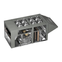
This document provides a quick start guide for the Greenheck Models RV and RVE, focusing on initial unit startup procedures for fans, energy wheels, cooling, and heating components. It emphasizes that this guide supplements, but does not replace, the full Installation, Operation, and Maintenance (IOM) manual, which should be consulted for all safety information and precautions. Pre-start checks and blower startup are prerequisites to following this procedure.
The guide outlines initial steps for fan setup, including verifying the discharge air sensor installation, ensuring proper phasing of incoming power (referencing Figure 1 for phase monitor indicator lights diagnostics and Figure 2 for a typical phase monitor), and energizing the unit's supply and optional exhaust fan by connecting terminals R to G, W1, Y1, and Y2 as applicable.
For blower operation, users must check rotation and reverse it if necessary by disconnecting and locking out power, then interchanging any two power leads to the motor. Motor amp draw must be checked against the motor nameplate FLA and recorded in a "Start-up Report." If the amp draw exceeds FLA, airflow should be reduced, and any changes made must be recorded. Excessive noise and vibration should be investigated by checking fasteners between the motor and impeller, motor and frame, frame and unit block-off, and ensuring they are tight. Contact between the impeller and inlet cone must also be checked.
For units equipped with an energy wheel, the guide instructs users to verify its rotation direction (noting that speed may vary by wheel model) and check its motor amp draw against the motor nameplate FLA, recording the reading in the "Start-up Report."
The cooling section provides a detailed, step-by-step process for each refrigeration circuit.
The guide provides a table of target refrigeration values:
The guide provides a table for gas pressure settings:
For customer support, the document provides the number 1-866-478-2574. The document is identified as RV and RVE Quick Start Guide, Rev. 4, October 2019, with copyright 2019 Greenheck Fan Corporation.
| Brand | Greenheck |
|---|---|
| Model | RV Series |
| Category | Air Conditioner |
| Language | English |