General Description - NOT model specificEnergy Recovery Ventilator with Heating and Cooling
32
Belt Drive Installation
1. Remove the protective coating from the
end of the fan shaft and assure that it is
free of nicks and burrs.
2. Check fan and motor shafts for parallel
and angular alignment.
3. Slide sheaves on shafts. Do not drive
sheaves on as this may result in bearing
damage.
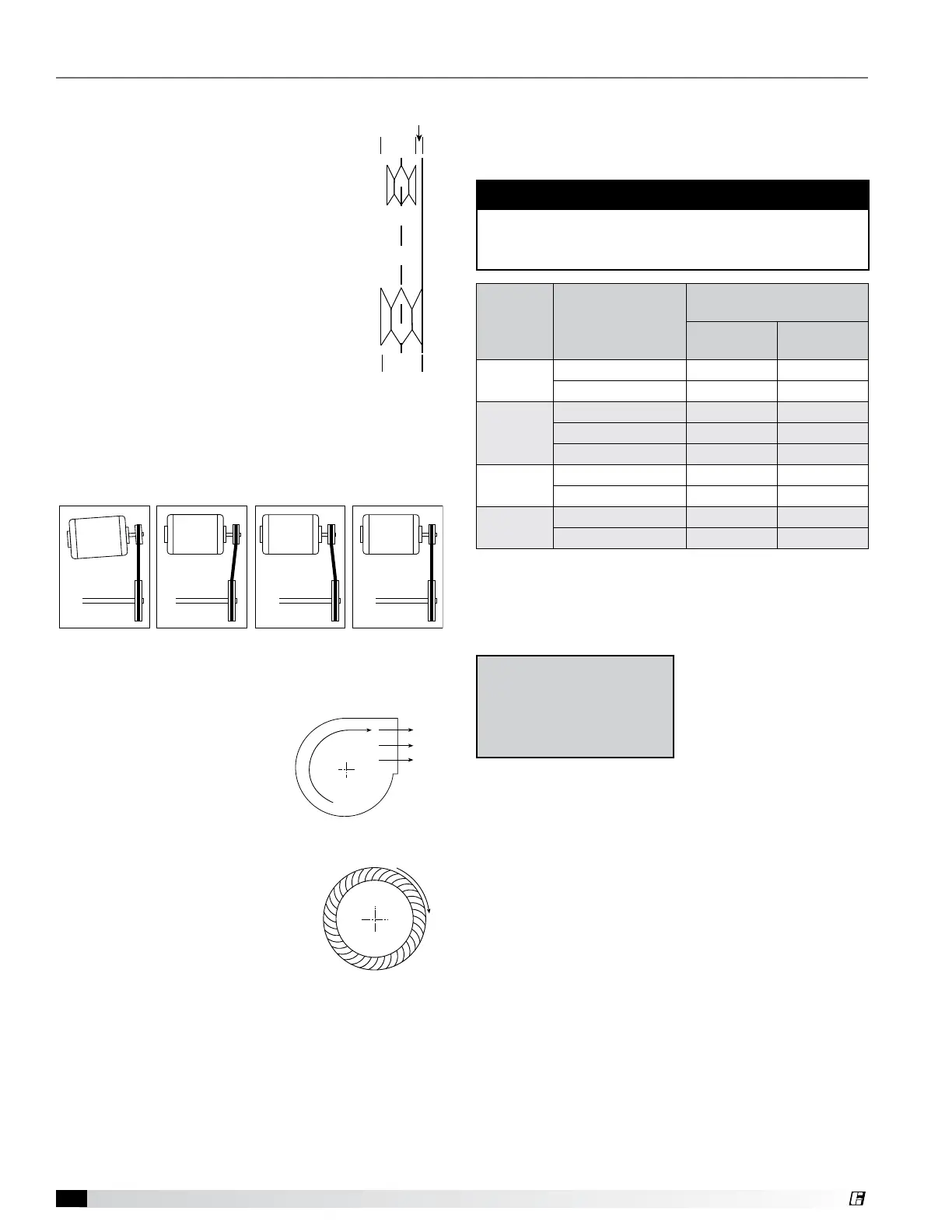
4. Align fan and motor sheaves with a
straightedge to centerline.
5. Place belts over sheaves. Do not pry
or force belts, as this could result in
damage to the cords in the belts.
6. With the fan off, adjust the belt tension
by moving the motor base. (See belt
tensioning procedures in the Routine
Maintenance section of this manual).
When in operation, the tight side of the belts should
be in a straight line from sheave to sheave with a
slight bow on the slack side.
Belt Span
Deflection =
Belt Span
64
WRONG WRONG
WRONG CORRECT
WRONG WRONG
WRONG CORRECT
Proper alignment of motor and drive shaft.
Direction of Fan Wheel Rotation
Blower access is labeled on unit.
Check for proper wheel rotation
by momentarily energizing the
fan. Rotation is determined
by viewing the wheel from the
drive side and should match the
rotation decal affixed to the fan
housing.
If the wheel is rotating the wrong
way, direction can be reversed
by interchanging any two of the
three electrical leads.
Check
for unusual noise, vibration, or
overheating of bearings. Refer to
the Troubleshooting section of this
manual if a problem develops.
Fan RPM
Supply fan and exhaust fan will have an adjustable
motor pulley (on 15 HP and below) preset at the factory
to the customer-specified RPM. Fan speed can be
increased or decreased by adjusting the pitch diameter
of the motor pulley. Multi-groove variable pitch pulleys
must be adjusted an equal number of turns open
or closed. Any increase in fan speed represents a
substantial increase in load on the motor. Always check
the motor amperage reading and compare it to the
amperage rating shown on the motor nameplate when
changing fan RPM. All access doors must be installed
except the control center door.
WARNING
Do not operate units with access doors open or
without proper ductwork in place as the fan motors
will overload.
Model
Blower Diameter
x Width
(inches)
Maximum RPM for
Forward-Curved Blowers
Class I
Max RPM
Class II
Max RPM
ERCH-20
10 x 6 1700 --
9 x 9 1750 2800
ERCH-45
9 x 9 1750 2800
12 x 8 1400 2000
12 x 12 1500 2000
ERCH-55
12 x 12 1500 2000
15 x 15 1250 1725
ERCH-90
15 x 15 1250 1725
18 x 18 1000 1450
Vibration
Excessive vibration may be experienced during initial
start-up and can cause a multitude of problems,
including structural and/or component failure.
Many of these conditions
can be discovered by
careful observation. Refer
to the Troubleshooting
section of this manual
for corrective actions.
If observation cannot locate the source of vibration, a
qualified technician using vibration analysis equipment
should be consulted. If the problem is wheel unbalance,
in-place balancing can be done.
Generally, fan vibration and noise is transmitted to other
parts of the building by the ductwork. To eliminate this
undesirable effect, the use of heavy canvas connectors
is recommended.
Hot Gas Bypass Valve (standard scroll)
To adjust, connect a pressure gauge to the suction line
and block the entering air to the evaporator coil. The
valve should begin to open when the suction pressure
drops to approximately 115 PSIG for R-410A (the valve
will feel warm to the touch). Adjustments are made by
first removing the cap on the bottom of the valve and
then turning the adjusting stem clockwise to increase
the setting pressure (counterclockwise to decrease).
Allow several minutes between adjustments for the
system to stabilize. When adjustment is complete,
replace the cap on the valve.
2 in.
1.5 in.
0.25 in.
centerline
straightedge
Pulley
alignment
example
Vibration Causes
Off axis or loose components
Drive component unbalance
Poor inlet / outlet conditions
Foundation stiffness
Backward Inclined
Forward Curved
Airflow
Airflow
Backward Inclined
(ERT)
Forward Curved
R
o
t
a
t
i
o
n
R
o
t
a
t
i
o
n
R
o
t
a
t
i
o
n
R
o
t
a
t
i
o
n
R
o
t
a
t
i
o
n
R
o
t
a
t
i
o
n
Backward Inclined
Forward Curved
Airflow
Airflow
Backward Inclined
(ERT)
Forward Curved
R
o
t
a
t
i
o
n
R
o
t
a
t
i
o
n
R
o
t
a
t
i
o
n
R
o
t
a
t
i
o
n
R
o
t
a
t
i
o
n
R
o
t
a
t
i
o
n
Start-Up Components
 Loading...