10
Energy Recovery Ventilator
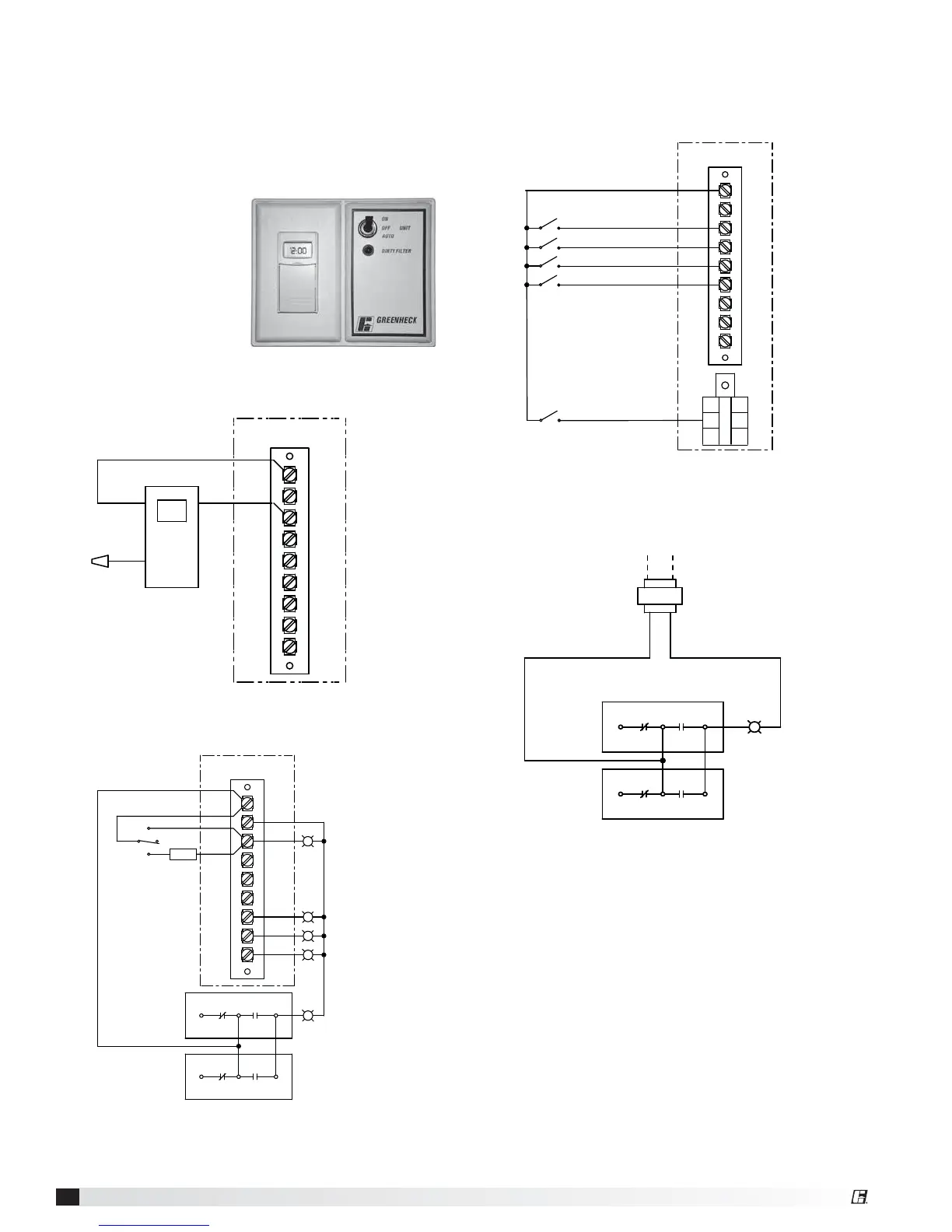
Optional Accessory Wiring Schematics
W1
12
7
6
Y2
Y1
G
C
R
TERMINAL BLOCKS IN
UNIT CONTROL CENTER
TIMER
BLACK BLUE
RED
(CAPPED)
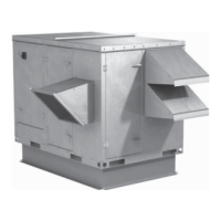
7-Day Timer
Remote Panel
The remote panel is available with a number of
different alarm lights and switches to control the unit.
The remote panel ships loose and requires mounting
and wiring in the field. The remote panel is available
with the following options:
• Unit on/off switch
• Unit on/off light
• 7-day time clock
• Hand/off/auto switch
• Dirty filter light
• Economizer light
• Frost control light
• Wheel rotation sensor light
NC
C
NC
C
NO
NO
DIRTY FILTER
EXHAUST DIRTY
FILTER SWITCH
SUPPLY DIRTY
FILTER SWITCH
HOT COMMON
Dirty Filter Indicator
(powered by others)
A
W1
12
7
6
Y2
Y1
G
C
R
UNIT ON/OFF
COOL STAGE 1 / ECONOMIZER
COOL STAGE 2
UNOCCUPIED RECIRCULATION
S1
S6
S7
S4
S5
HEAT
TERMINAL BLOCKS IN
UNIT CONTROL CENTER
Unit Interfacing Terminals
Heating/Cooling Switches & Night Setback
Switch/Timer
W1
12
7
6
Y2
Y1
G
C
R
NC
C
NC
C
NO
NO
UNIT ON/OFF
FROST CONTROL
ECONOMIZER
WHEEL ROTATION
DIRTY FILTER
ON
OFF
AUTO
*
* -- BMS, TIMECLOCK,
TERMINAL BLOCKS IN
UNIT CONTROL CENTER
ON/OFF/AUTO SWITCH ALLOWS THREE MODES OF OPERATION
"ON" - UNIT IS TURNED ON MANUALLY
"OFF" - UNIT IS TURNED OFF MANUALLY
"AUTO" - UNIT IS CONTROLLED VIA SCHEDULER OF BMS, TIMECLOCK, TSAT, ETC.
TSTAT, RTU, ETC.
EXHAUST DIRTY
FILTER SWITCH
SUPPLY DIRTY
FILTER SWITCH
On/Off/Auto Switch & Indictor Light Wiring