Installation, Operation and Maintenance Manual
Please read and save these instructions for future reference. Read carefully before attempting to assemble,
install, operate or maintain the product described. Protect yourself and others by observing all safety
information. Failure to comply with instructions could result in personal injury and/or property damage!
1
VGN Technology
®
®
Document 481885
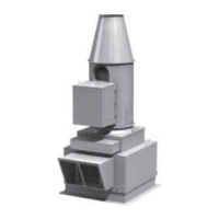
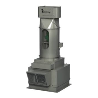
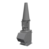
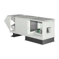
Vektor
®
Laboratory Exhaust
with Variable Geometry Nozzle (VGN) Technology
Electrical Controls Information
DANGER
Always disconnect power before working on or near a
unit. Lock and tag the disconnect switch or breaker to
prevent accidental power up.
CAUTION
When servicing the unit, variable frequency drives
(VFD) may be hot enough to cause pain or injury.
Allow motor to cool before servicing.
General Safety Information
Only qualified personnel should install this unit.
Personnel should have a clear understanding of these
instructions and should be aware of general safety
precautions. Improper installation can result in electric
shock, possible injury due to coming in contact with
moving parts, as well as other potential hazards. Other
considerations may be required if high winds or seismic
activity are present. If more information is needed,
contact a licensed professional engineer before moving
forward.
1. Follow all local electrical and safety codes, as well as
the National Electrical Code (NEC), the National Fire
Protection Agency (NFPA), where applicable. Follow
the Canadian Electrical Code (CEC) in Canada.
2. Do not allow the power cable to kink or come in
contact with oil, grease, hot surfaces, or chemicals.
Replace cord immediately if damaged.
3. Verify the power source is compatible with the
equipment.
Table of Contents
Receiving, Handling and Storage .................2
Variable Geometry Nozzle (VGN) Control System
Components ................................3
Quick Installation Guide .........................4
VGN System Function Overview
Mounting of VGN Controller ....................5
Nozzle to Pressure Transducer Box ..............5
VGN Controller to Pressure Transducer Box .......5
VGN Controller to VFD and BMS Hardwiring
Fan Run Signal ..............................6
BMS Communication .........................6
Nozzle Feedback ............................6
Fan Flow ..................................6
Outlet Velocity: On the Fly Unoccupied Adjustment 7
VGN Controller Incoming Power Wiring Instructions. . . 7
BMS Communication Programming
Fan Run Signal ..............................8
Nozzle Feedback ............................8
Fan Flow ...................................8
Alarm......................................8
Outlet Velocity: On the Fly Unoccupied Adjustment
and Example ............................8-9
Wiring Diagram - Single Fan and Multiple Fans . . 10-11
Start-Up Procedure
Mechanical Component System Verification ......12
Electrical Components System Verification .......12
System Start-Up Preparation for VGN ...........12
System Start-Up for VGN ..................12-13
Test and Balance for VGN ....................13
Calibrating Carel CFM Display with Test and
Balance Procedure ........................13
VGN Controller Introduction, Tutorial, Operator Interface
and Keypad Navigation ........................14
Status ....................................15
On/Off Unit ................................15
Set Points (Test and Balance)..................16
Clock/Scheduler ............................17
Inputs/Outputs ..........................17-18
Alarm History ..............................18
Technician .................................19
Factory ...................................20
Troubleshooting ..............................21
VGN Technology Maintenance...................22
VGN Technology Electrical Replacement Parts ......22
Maintenance Record ..........................23
Our Commitment ......................Backcover
Single Fan
VGN Controller
Multiple Fan
VGN Controller