8
VGN Technology
®
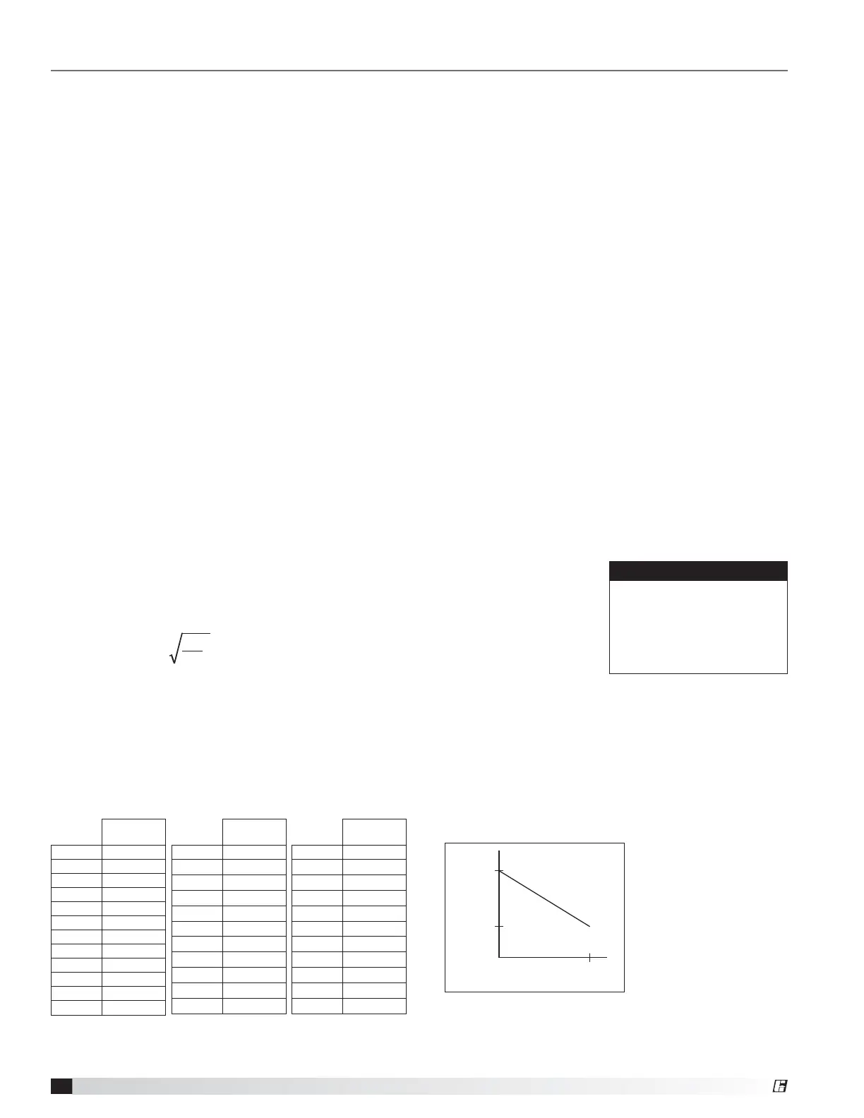
VELOCITY
VDC
0 10
3000
2000
DC Voltage to
Velocity Relationship
Sending 0 VDC to the B5 input on single fan or U5 input
on multifan of the Carel controller will default the nozzle
velocity to the maximum outlet velocity set by the user.
Sending 10 VDC to the B5 input on single fan or U5
input on multifan of the Carel will adjust the nozzle
velocity to the minimum outlet velocity set by the user.
Sending a DC voltage between 0 and 10 VDC will adjust
the nozzle outlet velocity linearly.
BMS Communication Programming
The VGN controller uses analog and digital
communications that are hard wired to the BMS to
communicate with the BMS.
Fan Run Signal can be switched by the BMS or VFD.
The VGN controller requires a 24 VAC fan run input
signal from BMS or VFD to communicate to the VGN
controller that the fan is running. Use a switching relay
contact controlled by the VFD or BMS to control the fan
run signal; the contact should be closed when the fan is
running. Multiple fan systems will require a separate fan
run signal for each fan which corresponds to each fan
number.
Nozzle Feedback will report the position of the
nozzle during operation. It is necessary to maintain
the minimum required nozzle outlet velocity. Each
nozzle has two feedback outputs, one for each blade
of the nozzle. The output from the nozzle feedback is a
2-10VDC voltage. To properly maintain required nozzle
outlet velocity the minimum allowable nozzle feedback
voltage is 2.1 VDC. If the nozzle feedback drops
below this voltage the fan speed must be increased to
maintain the required nozzle outlet velocity. Modulation
of the bypass damper may be required to maintain
proper duct pressure while maintaining required nozzle
outlet velocity.
Fan Flow This feature is not required for system
operation; this feature allows the BMS to record and
display the CFM of the fan during operation. Each fan
has one 0-10 VDC output for fan flow.
To calculate the fan flow and display it on the BMS use
the following calculations:
CFM = K-Factor •
ΔP
J
a. ΔP is calculated with the following equation:
((SURAIR Voltage)/10))*15
b.
J
is air density which is job site specific; a universal
number to use is .075 lbm/ft
3
c. K-Factor is listed on a data plate located on the fan
body or refer to the charts below; each fan type and
size have a unique K-Factor number.
NOTE: Repeat steps above for fan 2, 3, and 4 if
applicable.
Vektor-MS
(VK-M-XX)
Fan Size K-Value
15 526
18 787
20 955
22 1161
24 1436
27 1729
30 2116
33 2581
36 3154
40 3825
Vektor-HS
(VK-H-XX)
Fan Size K-Value
9 248
10 202
12 296
13 351
16 440
18 542
22 804
24 971
30 1463
36 2167
Vektor-CS
(VK-C-XX)
Fan Size K-Value
12 296
15 431
18 542
22 805
24 982
27 1184
30 1464
33 1770
36 2168
40 2630
44 3220
Alarm The alarm will notify the BMS of issues with
the VGN control system by closing a dry relay contact
within the Carel controller. There is only one alarm
contact for the entire VGN control system regardless of
the number of fans. The Carel controller located in the
VGN control box will display the alarm history to help
diagnose the issue; no alarm history will be transmitted
to the BMS.
The alarm contact will close due to the following issues:
The fan run signal shows the fan running but the
0-10VDC signal from the pressure transducer is not
within the expected range. This could be due to wiring
issues, failed pressure transducer, closed isolation
damper, water in the pressure transducer tubes, or the
fan motor is not spinning.
Outlet Velocity: On the Fly Unoccupied
Adjustment
This feature is not required for system
operation. This feature allows the user to adjust the
nozzle outlet velocity remotely while the fan is running
with the use of a 0-10 VDC signal sent from the BMS
to the VGN controller. This feature is used to reduce
energy costs during unoccupied or low use lab times.
It can also be used with real time wind wake study
data to optimize energy consumption. Lower nozzle
velocity will equate to lower plume height and lower
system restriction; it is the responsibility of the user to
determine what nozzle velocity is required.
In the “User Settings”
menu of the Carel menu,
the user can set the
nozzle outlet velocity
maximum and minimum
settings.
USER SETTINGS
ELEVATION: 0 FT
MAX OUT VEL: 3000 FPM
MIN OUT VEL: 2000 FPM
ACTIVE STPT: 3000 FPM
FOR TEST/BALANCE
PRESS DOWN ARROW
 Loading...