7
VGN Technology
®
VGN Controller Incoming Power
Wiring Instructions
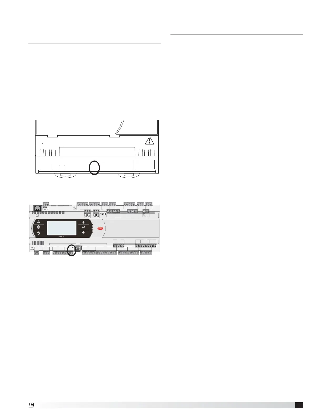
Incoming Power (hard wire connections)
The VGN controller will function on 120, 208, 240, or
480V single-phase 50/60 Hz AC. Remove the metal
cover located on the right side of the VGN controller to
access the terminal strip for incoming power (reference
Wire Diagram for details on terminal strip landing
points). Once the wiring is complete reinstall the metal
cover. Each VGN controller will draw a maximum of
2amps.
Variable Geometry Nozzle (VGN)
Controller to VFD and BMS
Hardwiring Instructions
- continued
NOTE: There is only one on the fly unoccupied nozzle
velocity adjustment for the entire VGN control system
regardless of the number of fans; one BMS signal
commands all the nozzles to the same outlet velocity.
C1
NO1
NO2
NO3
C1
C4
NO4
NO5
NO6
C4
C7
NO7
C7
NO8
C8
NC8
NO12
C12
NC12
NO13
C13
NC13
C9
NO9
NO10
NO11
C9
G
G0
U1
U2
U3
GND
+VDC
+Vterm
GND
+5 VREF
U4
GND
U5
GND
VG
VG0
Y1
Y2
Y3
Y4
ID1
ID2
ID3
ID4
ID5
ID6
ID7
ID8
IDC1
U6
U7
U8
GND
ID9
ID10
ID11
ID12
IDC9
ID13H
ID13
IDC13
ID14
ID14H
J1
J24 J2 J3
J4 J5
J7
J8
J20
J21
J14
J10
J13J12
J22
J16
J17
J18
J15
J6
J19
NO14
C14
NC14
NO15
C15
NC15
C16
NO16
NO17
NO18
C16
ID15H
ID15
IDC15
ID16
ID16H
Y5
Y6
ID17
ID18
IDC17
U9
GND
U10
GND
drac SMBdrac suBdleiF
J23 FBus2
J11 pLAN
J25 BMS2
J26 FBus2
43 21
Outlet Velocity: On the Fly Unoccupied
Adjustment
This feature is not required for system
operation. This feature allows the user to adjust the
nozzle outlet velocity remotely while the fan is running
with the use of a 0-10 VDC signal sent from the BMS
to the VGN controller. Connect the BMS directly to the
proper input (see below) on the Carel PLC unit and
COM on the terminal strip.
Wire Landing Points
• Single Fan Entire System: B5 on Carel PLC and COM
on the terminal strip
• Multifan Entire System: U5 on Carel PLC and GND
on the Carel PLC
J1
G
G0
+5Vref
+VDC
ID1
GND
J3
C1
NC1
NO1
J2
SYNC
B1
B2
B3
B4
B5
B6
GND
serial card 1
24 V (+10/-15%); 50/60 Hz
48 V (36Vmin…72 Vmax)
input voltage: max. power:
8 VA / 6 W
 Loading...