18
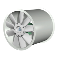
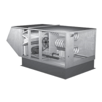
Energy Recovery Ventilator
Variable Frequency Drives
Optional factory installed, wired, and programmed
variable frequency drives (VFDs) may have been
provided for modulating or multi-speed control of the
blowers and energy recovery wheel for economizer
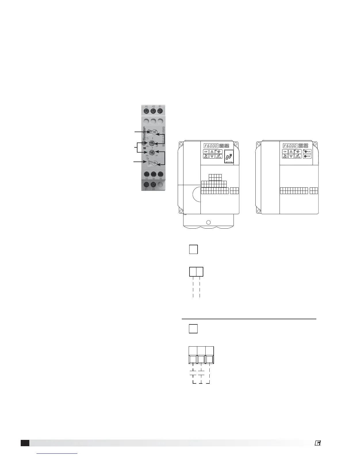
and frost control modes. One VFD, either Yaskawa
model V1000 or J1000, is provided for each blower
(supply air and exhaust) and one Yaskawa model
J1000 is provided for the energy recovery wheel.
Refer to the tables in this section for factory settings
and field wiring requirements. Refer to the unit control
center for unit specific wiring diagram. When making
adjustments outside of the factory set points, refer to
Yaskawa VFD instruction manual, which can be found
online at www.drives.com. For technical support,
contact Yaskawa direct at 1-800-927-5292.
OPTION 1 - 0-10 VDC CONTROL
SEE VFD INSTALLATION MANUAL FOR MORE DETAIL
USER TO PROVIDE ISOLATION AS REQUIRED
FOR CONTINUOUS 60Hz OPERATION JUMPER TERMINALS A1 AND +V.
WIRED TO A1 (+) AND AC (COMMON)
0-10 VDC CONTROL SIGNAL (BY OTHERS)
10 VDC = 60 Hz
0 VDC = 30 Hz
A1 AC
FOR ONE 0-10 SIGNAL, WIRE TO DRIVES IN PARALLEL
OPTION 2 - MULTI SPEED CONTROL
S5S4 SC
NEITHER S4 OR S5 CONTACT CLOSED
DRIVE SPEED = 60 Hz.
DRIVE SPEED = 40 Hz.
S4 TO SC CONTACT CLOSED (BY OTHERS)
S5 TO SC CONTACT CLOSED (BY OTHERS)
DRIVE SPEED = 30 Hz.
TO CHANGE THE FACTORY SET Hz CHANGE THE FOLLOWING PARAMETERS.
PARAMETER A1-01 CHANGE TO 2
PARAMETER d1-02 FOR NEW 40Hz SETTING
PARAMETER d1-01 FOR NEW 60Hz SETTING
PARAMETER d1-03 FOR NEW 30Hz SETTING
PARAMETER A1-01 CHANGE TO 0
USER TO PROVIDE CONTACTS AND ISOLATION AS REQUIRED
SEE VFD INSTALLATION MANUAL FOR MORE DETAIL
Frost Control
Timed Exhaust
1. Remove power from unit.
2. Jumper the frost indicating wheel pressure switch
in the unit control center.
3. Jumper the temperature indicating thermodisc in
the unit control center. Thermodisc has a pre-set
temperature of 5ºF.
4. Set the frost control timer scale for T1 and T2 to
1m. Set the timer settings for T1 and T2 to 10.
5. Add power to the unit. Blower
should cycle on for one minute,
then turn off for one minute.
6. Remove power from unit and
remove jumpers that were
placed. Re-set timer settings.
• T1 timer setting set to 5 and
timer scale set to 10m for 5
minutes of wheel off time.
• T2 timer setting set to 5 and
timer scale set to 1h for 30
minutes of wheel on time.
Electric Preheat
1. Remove power from unit.
2. Jumper the frost indicating wheel pressure switch
in the preheat control center.
3. Jumper the temperature indicating thermodisc in
the preheat control center. Thermodisc has a pre-
set temperature of 5º F.
4. Apply power to unit. Preheater should turn on.
Timer
Scale
Timer
Scale
Timer
Settings
T1
T2
MA MB MCRPH1SCHCS7S6S5S4S3S2S1
MPACAMAC+VA2A1PCP2P1
IGS-S+R-R+
V1000
MA MB MCACAMAC+VA1SCS5S4S3S2S1
J1000