16
NOTE
Large evaporative coolers may require a separate
power supply.
6. Wire the Evaporative Cooler (optional)
Reference the ladder diagram on the inside of the
control center door for correct wiring of the pump and
the optional water valves.
7. Install Economizer Sensors (optional)
All economizer options (EC) require an outdoor air
temperature or enthalpy sensor to be field installed
inside of the weatherhood and field wired to terminals
SO+ and SO- on the economizer.
Economizer options EC-3 and EC-4 require an outdoor
air temperature or enthalpy sensor to be field installed
in the return air duct and field wired to terminals SR+
and SR- on the economizer.
The sensors are provided by the factory and ship with
the unit.
8. Install Discharge Air Sensor (optional)
For units with 8:1, 16:1 or 24:1 staged turndown,
install the discharge air sensor at least three duct
diameters downstream of the heat exchanger. The
discharge air sensor can be found in the unit’s control
center.
9. Install DDC Interface (Optional)
Some units may use an external signal from a building
management system to control the dampers and/or
discharge air temperature. Reference the unit ladder
diagram for the correct wiring.
®
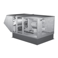
Model IG / IGX Make-Up Air