Do you have a question about the Greenheck Vektor-H Series and is the answer not in the manual?
Details concrete deck anchoring, including bolt type, embedment, and edge distance requirements.
Specifies timber anchoring methods, lag bolt requirements, and installation distances.
Outlines steel anchoring with self-drill/tap fasteners, detailing dimensions and engagement.
Details steel anchoring using thru bolts, including bolt size, edge distance, and curb distance.
Fastener requirements for 1x1 or fan only curb installation, including corner and equally spaced fasteners.
Fastener specifications for 2x1 or 3x1 curb types, detailing angle and fastener placement.
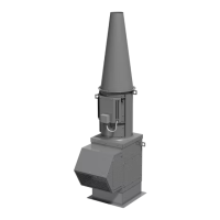
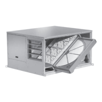
This document outlines the installation, operation, and maintenance procedures for Greenheck Vektor-H and Vektor-HS fans, specifically referencing their Miami-Dade Notice of Approval (NOA) Certification per NOA No. 19-0520.03. The manual emphasizes the importance of adhering to these instructions to ensure product warranty validity, prevent personal injury, and avoid property damage. It serves as a critical guide for anyone involved in the assembly, installation, operation, or maintenance of these ventilation systems.
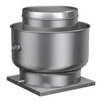
The primary function of the Greenheck Vektor-H and Vektor-HS fans is to provide ventilation, likely in commercial or industrial settings, given the robust anchoring methods described. These fans are designed to be installed with a Greenheck model GPFHD curb, which acts as an interface between the fan unit and the building structure. The installation instructions detail various anchoring methods suitable for different building materials, ensuring secure and compliant mounting.
The manual focuses heavily on the installation aspect, which is a critical initial step for the proper functioning of the fan. The detailed anchoring instructions highlight the versatility of these fans for different construction types:
A crucial usage feature is the requirement for all fasteners to be installed according to the manufacturers' instructions, which underscores the importance of precision and adherence to specific product guidelines for optimal performance and safety.
The manual also provides a comprehensive table detailing the "MINIMUM NUMBER OF FASTENERS PER SIDE TO ATTACH CURB TO STRUCTURE (excludes 4 corner fasteners)." This table is broken down by fan model (Vektor-H-9 through Vektor-H-36) and anchoring method (Concrete Deck, Steel Thru Bolts, Timber, Steel Self-Drill/Tap). For each method, it specifies the number of fasteners required for 1x1 or fan only, 2x1, and 3x1 curb configurations. This level of detail ensures that installers can select the correct number of fasteners based on the specific fan model and installation scenario, guaranteeing structural integrity. For instance, a Vektor-H-12 fan installed on a concrete deck with a 2x1 curb requires 9 fasteners, while the same fan on timber with a 3x1 curb needs 16 fasteners.
Furthermore, the document specifies the use of "ONE 2 in. x 2 in. x 1/4 in. SQUARE WASHER UNDER ALL FASTENERS," which is a critical detail for distributing the load and preventing fastener pull-through, thereby enhancing the overall stability and longevity of the installation.
The curb fastener diagrams illustrate how the Greenheck model GPFHD curb should be attached. For "1X1 OR FAN ONLY CURB" configurations, there is "One fastener in each corner" and "1x1 min. number of fasteners" that are "Equally spaced" along the sides. A "5 in. flange" is shown, and a "1-3/8 in. max distance from vertical face of curb" is specified. An "Angle, one per side A1018 CS, 5 in. x 2 in. x 5/16 in. thick" is also depicted, with a "Length equal to actual outside length of curb." For "2X1 OR 3X1 CURB" configurations, similar principles apply, with fasteners in each corner and equally spaced along the sides, maintaining the "5 in. flange" and "1-3/8 in. max distance from vertical face of curb." These diagrams are essential for visual guidance during installation, ensuring correct fastener placement and spacing.
While the document primarily focuses on installation, the phrase "Installation, Operation and Maintenance Manual" in the title indicates that maintenance is an integral part of the device's lifecycle. Although specific maintenance schedules or procedures are not detailed within the provided pages, the emphasis on proper installation directly contributes to reduced maintenance needs and extended operational life. A correctly installed fan, using the specified fasteners and anchoring methods, is less likely to experience premature wear, vibration issues, or structural failures that would necessitate frequent repairs.
The warning "Failure to comply with these instructions will result in voiding of the product warranty and may result in personal injury and/or property damage" strongly implies that ongoing maintenance, as outlined in the full manual (beyond these excerpts), is crucial for ensuring the fan's safe and efficient operation over time. This also suggests that any maintenance activities must adhere to Greenheck's guidelines to maintain warranty coverage. The robust installation methods described are foundational to a low-maintenance operational profile, as they prevent common issues arising from poor initial setup.
In summary, the Greenheck Vektor-H and Vektor-HS fans are designed for versatile and secure installation across various building materials, ensuring high performance and compliance with stringent standards like Miami-Dade NOA. The detailed instructions for anchoring, fastener selection, and curb attachment are key usage features that facilitate proper setup. While specific maintenance steps are not detailed in these excerpts, the manual's overall scope and the emphasis on correct installation underscore the importance of ongoing care for the device's longevity and warranty validity.
| Fan Type | Centrifugal |
|---|---|
| Drive Type | Direct |
| Wheel Material | Aluminum |
| Housing Material | Steel |
| Wheel Type | Backward Inclined |
| Drive Types | Direct Drive |
| Temperature Range | -40°F to 250°F |