773 and 774 Ratchet Cable Cutters
Greenlee / A Textron Company 10 4455 Boeing Dr. • Rockford, IL 61109-2988 USA • 815-397-7070
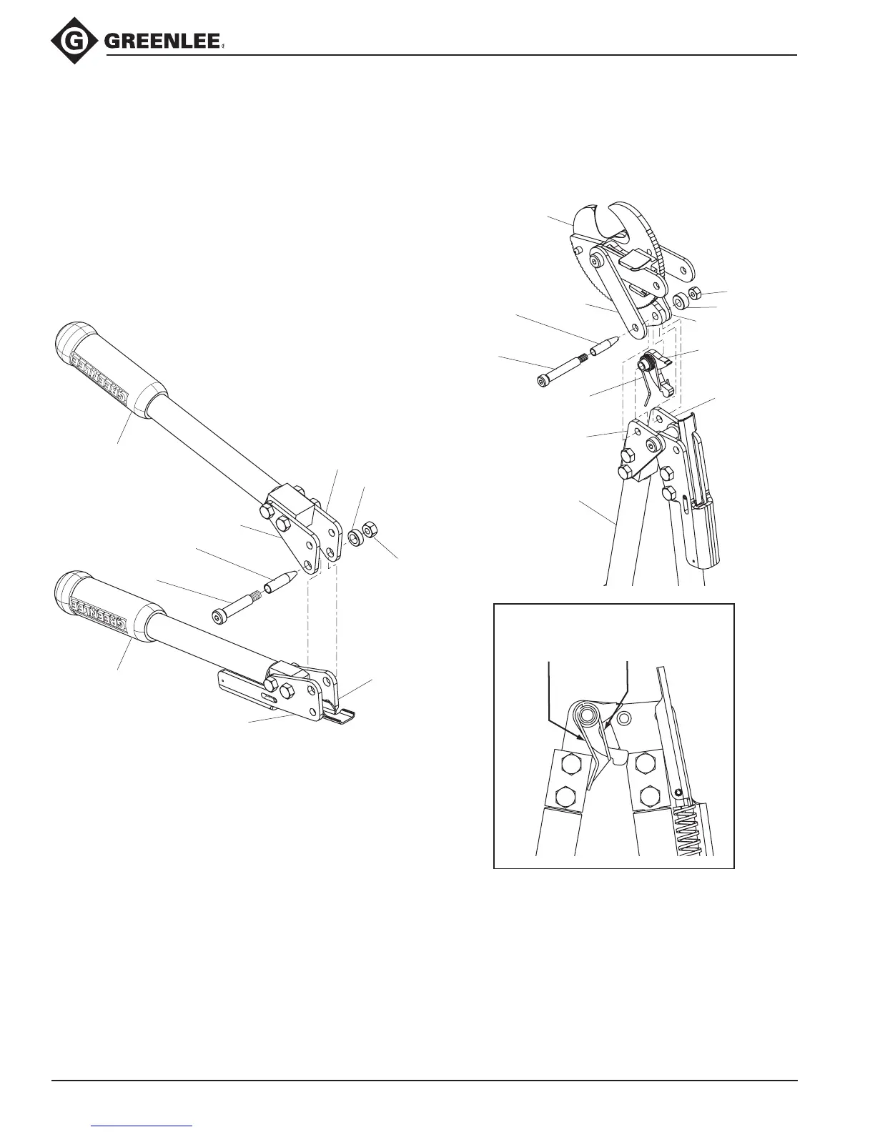
Assembly (cont’d)
Movable handle to stationary handle
15. Install movable handle assembly between the
stationary handle plates and align the 3/8" pivot
holes.
16.
Install optional screw guide (46) onto shoulder screw
(13) to help guide the screw through components.
17. Lubricate shoulder screw (13) and install it through
the handle plates (5 and 8), handle plates (9 and
5) and spacer (26). Remove guide (46) if used and
install lock nut (23).
Cutter head to stationary handle
18. Install torsion spring (40) onto holding pawl (6)
and locate them between the handle plates on the
stationary handle (39) as shown.
19. Install head assembly between handle plates on the
stationary handle and around the holding pawl (6).
20. Install optional screw guide (47) onto shoulder screw
(16) to help guide the screw through components.
21. Lubricate shoulder screw (16) and install it through
link (4), handle plate (5), torsion spring (40), holding
pawl (6), stationary blade (2), second handle plate (5),
cover (10) and spacer (19). Remove guide (47)
if used and thread on lock nut (24), but do not
tighten.
2
4
40
5
39
5
6
10
19
24
47
(optional)
16
Note:
Ends of torsion spring should be
against handle and pawl as shown.
5
26
23
5
stationary handle
assembly
9
movable handle
assembly
8
46
(optional)
13