DVC-6 • DVC-10
7
Operation
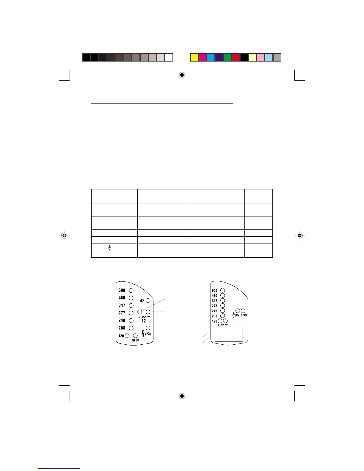
1. See Typical Measurements for illustrations.
2. See the Test Table for test instructions.
3. Test the unit on a known functioning circuit or component.
• If the unit does not function as expected on a known functioning circuit, replace the
batteries.
• If the unit still does not function as expected, send the unit to Greenlee for repair.
4. Take the reading from the unit to be tested. The LEDs illuminate as follows:
LED Table
LED Illuminated
Indication
Tone
DVC-6 DVC-10
LED 1
Positive (+) DC Positive (+) DC
None
of 12 V or more of 120 V or more
LED 2
Negative (–) DC Negative (–) DC
Continuous
of 12 V or more of 120 V or more
LED 1 and LED 2 AC of 12 V or more AC of 120 V or more Warbling
Other Voltage LEDs Approximate voltage level —
/ Rx Continuity or voltage present *
GFCI GFCI test in progress —
DVC-6
LED 1
LED 2
DVC-10
LED 1
LED 2
*Continuous tone for continuity. Tone for voltage is described above.