Do you have a question about the Greenwood Vireo HR155WM and is the answer not in the manual?
| Model | Vireo HR155WM |
|---|---|
| Brand | Greenwood |
| Category | Fan |
| Duct Diameter | 150mm |
| IP Rating | IP44 |
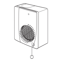
Describes the Vireo system as a ventilation unit for improved indoor air quality using heat recovery.
Lists required ancillary items for Vireo HR155WM/HR155CM and HR185WM models.
Lists the contents of the Vireo unit packaging, including the unit, bracket, and guides.
Safety warning about appliance use by children and persons with reduced capabilities.
Advises on safety precautions when working at height and wearing eye protection.
States the product should be handled as electronic waste and details disposal options.
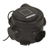
Provides front and side view diagrams with dimensions for the Vireo HR155WM unit.
Provides front and side view diagrams with dimensions for the Vireo HR155CM unit.
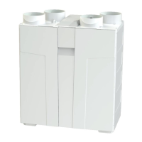
Provides front and side view diagrams with dimensions for the Vireo HR185WM unit.
Details ducting requirements and installation standards for compliance.
Important note on preventing backflow of gases from fuel-burning appliances into living areas.
Provides guidance on vertical and horizontal installation positioning for different Vireo models.
Advises against installing the unit directly above living or sleeping areas.
Emphasizes the need for adequate access for servicing, maintenance, and fault diagnostics.
Explains unit configuration for right and left-hand installation via software.
Illustrates ducting connection configurations for the Vireo HR155WM unit.
Illustrates ducting connection configurations for the Vireo HR155WM unit.
Illustrates ducting connection configurations for the Vireo HR155CM unit.
Illustrates ducting connection configurations for the Vireo HR185WM unit.
Details the wall fixing bracket supplied for HR155WM and HR185WM units.
Guides on aligning the wall bracket considering wall space and unit weight support.
Details the adjustable ceiling fixing brackets supplied for the HR155CM unit.
Warning to ensure ceiling board can support the unit's weight (20kg for HR155CM).
Explains how the unit attaches to the ceiling bracket using slotting and sliding mechanisms.
Instructs on securely fitting the unit by tightening screws after initial placement.
Shows the required maintenance access space for wall-mounted Vireo HR155WM.
Shows the required maintenance access space for ceiling-mounted Vireo HR155CM.
Shows the required maintenance access space for wall-mounted Vireo HR185WM.
Stresses the importance of condensate drainage and details drain locations for different models.
Specifies requirements for condensate drain installation, including fall and U-bend.
Important note on incorporating a U-bend in the condensate drain to prevent smells and freezing.
Advises referring to design drawings for the proposed ducting layout.
Details the number and sizes of spigots provided for ducting connections on Vireo units.
Mandates fitting Fire Dampers in accordance with Building Regulations for safety.
Provides guidelines for installing rigid ducting, focusing on minimizing resistance and ensuring airtightness.
Provides guidelines for installing flexible ducting, emphasizing tautness and avoiding crushing.
Specifies that intake fresh air should be sourced directly from outside, with grille requirements.
Details requirements for exhaust air exit to the outside, including protected terminals.
Advises installing intake and exhaust pipes at least 1m apart to prevent airflow cross-contamination.
Strong warning that the appliance must be earthed and wiring must conform to BS7671.
States that electrical installation must be performed by a qualified electrician.
Specifies that units are suitable for a 230V~50Hz single phase supply fused at 3A.
Mandates use of a triple-pole switch with 3.0mm contact separation for unit isolation.
Lists recommended switches (GS2, GRC1) for controlling the Vireo unit.
Presents the wiring specification diagram for connecting the unit to a 2-position switch.
Provides instructions on accessing and wiring to the BMS connector on the unit's PCB.
Provides instructions on accessing and wiring to the BMS connector on the unit's PCB.
Warning to use the cable grommet for BMS connection to prevent water ingress.
Details how to remove and wire the BMS terminal block, including pin functions.
Shows a close-up of the PCB, highlighting BMS connection points and pin assignments.
Illustrates the GRC1 controller and its connection to the Vireo unit via BMS.
Provides a wiring diagram for connecting the Vireo unit to a BMS system.
Instructions on securing BMS wiring using the cable clamp after completion.
Guides on refitting the electrical cover, ensuring the gasket seal is correctly seated.
Introduces the section covering unit setup, configuration, and altering factory settings.
Details initial steps for commissioning: checking wiring and switching on the mains supply.
Describes the integral LCD display used for unit control and configuration.
Provides examples and explanations of screens seen during the commissioning wizard.
Guides on setting up port configuration, choosing between RH and LH.
Details setting the extract airflow rate at high speed.
Details setting the supply airflow rate at high speed.
Details setting the extract airflow rate at low speed.
Details setting the supply airflow rate at low speed.
Guides on setting up the Greenwood HumidiSMART™ feature (ON/OFF).
Guides on setting up the Greenwood TimerSMART™ feature (ON/OFF).
Final steps for completing the commissioning wizard and exiting.
Details steps for setting up extract and supply air valves for optimal performance.
Instructs on measuring total air volume at extract valves and regulating flow per room.
Guides on checking system operation after commissioning using switches and controllers.
Guides on checking system operation after commissioning using switches and controllers.
Explains how to verify performance levels at extract and supply air valves using measurement tools.
Presents performance graphs showing airflow characteristics for HR155WM and HR155CM models.
Presents performance graphs showing airflow characteristics for the HR185WM model.
Explains how to re-activate the commissioning wizard to make adjustments after initial setup.
Guides on modifying the summer bypass activation temperature for comfort control.
Guides on modifying the summer bypass activation temperature for comfort control.
Declares the performance specifications for the Greenwood Vireo HR155WM unit.
Provides Specific Energy Consumption, Annual Electricity Consumption, and Annual Heating Saved data.
Provides Specific Energy Consumption, Annual Electricity Consumption, and Annual Heating Saved data for HR155CM.
Provides Specific Energy Consumption, Annual Electricity Consumption, and Annual Heating Saved data for HR185WM.
States that the Greenwood Vireo product comes with a 2-year guarantee.
Provides contact details for obtaining full guarantee information.